TAGGED: 3d-solids, ansys-ls-dyna, connection
-
-
September 18, 2024 at 6:11 am
mostafam
SubscriberHi
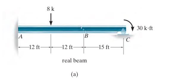
Here is a determinate beam which is fix supported from the left and pin supported on the right. Point B is an internal hinge where the bending moment is equal to zero. Modeling such problem using beam element in LS-DYNA is easy and I was able to do that. But, because of verification purposes I need to model the same problem using solid elements instead of beams. In order to apply the hinge at point B, I am looking for a proper way.
I have tried to apply discrete zero length beam instead of the hinge, but I was not successful in verifying the hand calculations. Has anybody modeled such hinge connection between two solid element in LS-DYNA before?
Thanks
-
September 19, 2024 at 2:02 pm
Ram Gopisetti
Ansys EmployeeHi
When you say hinge, you have two methods,
CNRB approach: create a CNRB ( constrained nodal rigid bodies) connection between two solid parts and then resolve the components via (Boundary_ prescribe _ motion_rigid infer the PID of this CNRB )such that rotation is free and the rest of the components are 0
Joint approach: you can model the revolute joint as given in the link
Also, on a simple approach, you can use the SPC with a Rotational component to 0
Happy Simulation,
Ram.
-
- You must be logged in to reply to this topic.


-
2773
-
965
-
841
-
599
-
591

© 2025 Copyright ANSYS, Inc. All rights reserved.


