

Tagged: Design Verifier, Formal methods, Proof, Requirements, SCADE, SUITE, Test, V&V
-
-
December 8, 2025 at 3:19 pm
 SolutionParticipant

This blog is part of a series on formal verification of applications developed with SCADE Suite. If you are new to model checking or want an overview of the SCADE Suite Design Verifier tool, we recommend starting with this blog : Introduction to formal verification and SCADE Suite Design Verifier.
Introduction
Modern aircraft, railway and automotive systems contain complex software with millions of lines of code, many of them performing functions that are critical to the safe transport of passengers. When developing these systems, quality assurance is paramount as software must be verified to function correctly with the highest levels of assurance, and the manufacturers must always demonstrate evidence of correctness through a rigorous certification process, especially in the aerospace and railway industries.
Testing plays a key role in ensuring software quality by guaranteeing that software fulfills defined requirements and delivering functional products that meet user expectations. However, with the increasing size and complexity of software in modern transport systems, testing is becoming more expensive and accounts for a significant portion of the overall cost of software development. Furthermore, when it comes to testing software, it can be difficult to determine when to stop, as testing only identifies the known defects or design errors and provides no indication of unknown defects.
Consider for example, a small arithmetic function with two integer inputs. A plethora of test cases would be required to test all possible execution paths of this function, with no guarantee of covering all possibilities without missing anything. To overcome these issues, a formal verification technique such as model checking could be used, as it allows the execution paths of software to be fully explored and design errors to be detected. With its ability to detect errors in the early development process of a software function, model checking has a clear impact on downstream costs of software development as it is much easier and less expensive to fix errors during the design phases than during implementation and integration phases. In the aerospace and railway industries, model checking is well known to provide a high level of assurance for the correctness of software components that implement safety-critical functions, and it is supported by certification guidance such as DO-178C and EN-50716 to satisfy certification objectives of software.
In our previous blog, we illustrated how model checking can be performed with SCADE Suite Design Verifier, a model checking tool based on Prover PSL ™ to prove that your software applications are free of common runtime errors that may be hidden in your software design. In this blog, we will show how the tool can be used to prove that a software design implements effectively its functional and safety requirements.
Application Example: Slip-Slide Detection System
In the railway sector, monitoring train wheel axles is important to prevent a slipping and sliding phenomenon that could cause catastrophic hazards. A system that detects wheel slip and slide is characterized as a SIL 4 system, which corresponds to the highest level of safety in railway operations. While designing software for a slip-slide detection system, SCADE Suite Design Verifier can be used to fully explore the software behavior in order to prove that the software effectively implements its requirements. For this purpose, let us consider a SCADE Design that illustrates control software specification for wheel slip and slide detection. As depicted in Figure 1, this software takes as inputs the train speed and wheel axle speeds and it returns the detection system state, the axle speed state and the detection result for each axle.
The software performs two main tasks. On one hand, it permanently checks if the train is in movement and switches on the slip-slide detection system when the train is in movement. On the other hand, it checks if all axle speeds are identical to the train speed and if it is not the case, it detects the kind of deviation (slip or slide) on each axle. In this example, we consider that an axle slips when its speed is greater than the train speed within a given threshold for at least a specific number of consecutives cycles (
NbCycles) and it slides when its speed is lower than the train speed with the same assumptions.

Figure 1. Slip-Slide Detection Software specificationLet us consider the set of functional and safety requirements listed in Table 1 and let us verify that our software effectively implements these requirements with SCADE Suite Design Verifier (SCADE DV).

Table 1. Slip-Slide Detection Software RequirementsFormal Verification workflow for software requirements
Now let us illustrate the formal verification workflow for software requirements with SCADE DV. For this purpose, we will consider project SpeedParallelism that contains the specification of our slip-slide detection software.
Figure 2 shows the steps to perform the formal verification of software requirements with SCADE DV.

Figure 2: User error verification workflow with SCADE Suite Design VerifierStep 1: Identify the requirements that shall be verified and define properties
Before running any verification, the requirements that need to be verified should clearly be identified and, similarly to the specification of test cases for testing, verification properties must be defined using these requirements. Verification properties are axioms that implement the interfaces of the software under verification and provide more details on how the requirements must be verified.
Several properties can be defined to verify the same requirement as illustrated in Table 2 where the properties “slip detection” and “slide detection“ are defined to verify the effective implementation of the functional requirement #Req2. One can also specify a property that implements multiple requirements.

Table 2. Slip-Slide Detection Software Requirements and related verification propertiesStep 2: Enable SCADE DV
To enable SCADE DV, you can either create a verification project, which uses the design project SpeedParallelism as a library or you can directly enable SCADE DV in the design project and create a package for the verification modules.
If you choose to create a verification project, then you should follow the steps illustrated by Figure 3:
- Go to the File Tab and click New (or Press Ctrl+N).
- From the New Panel, go to the project Tab and select SCADE Suite project for Design Verifier.
- Fill in the name and the location path of your project and click OK. Note that during the creation of your project, you can choose to link the project to an existing workspace or automatically generate a new one.
- Select your design project and insert it as a library in the newly created project.
In case you prefer to enable SCADE DV in your design project instead of creating a verification project, then you should follow the steps illustrated in Figure 4:
- In the FileView or ScadeView Panel, select the active Scade project.
- From the Project tab, click “Enable Design Verifier”
- In the popup window, click OK and verify that filename.I4 is created.
Note: When you enable SCADE DV on your design project, you need to insert manually the built-in library “libverif” which consists of utility blocks for specifying verification properties. Moreover, once SCADE DV is enabled, you will get the Design Verifier view, where you can specify proof objectives and verification strategies. In the fourth step of the verification workflow, we will see how one can specify user proof objectives and verification strategies.
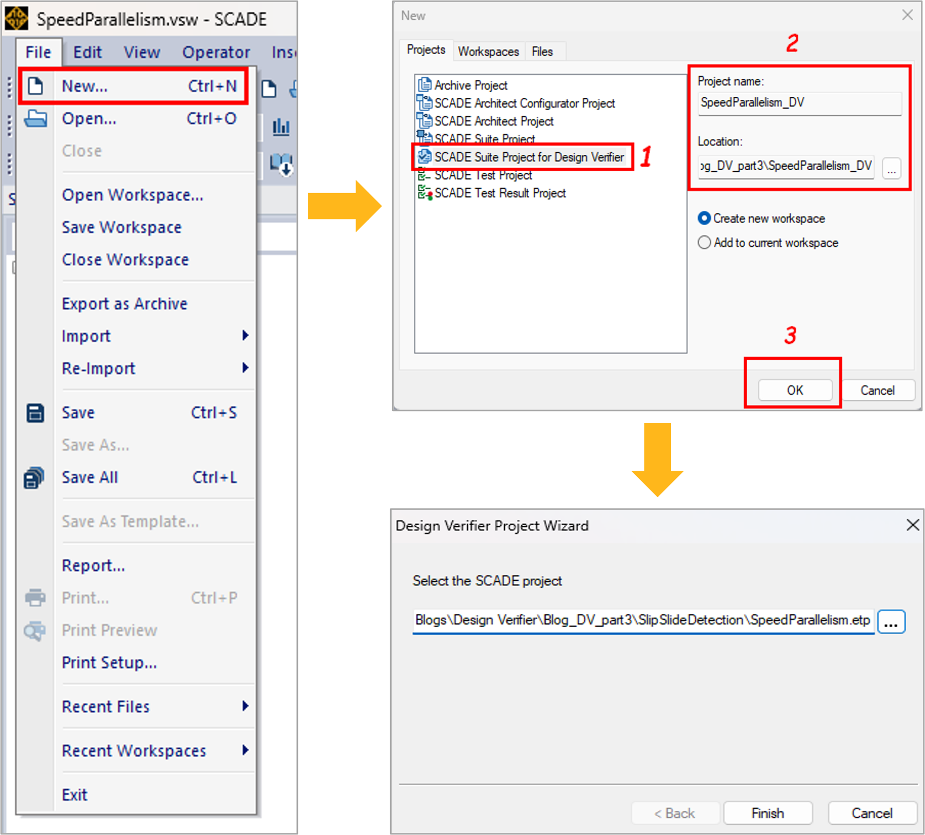
Figure 3: Creating a SCADE Suite project for Design Verifier
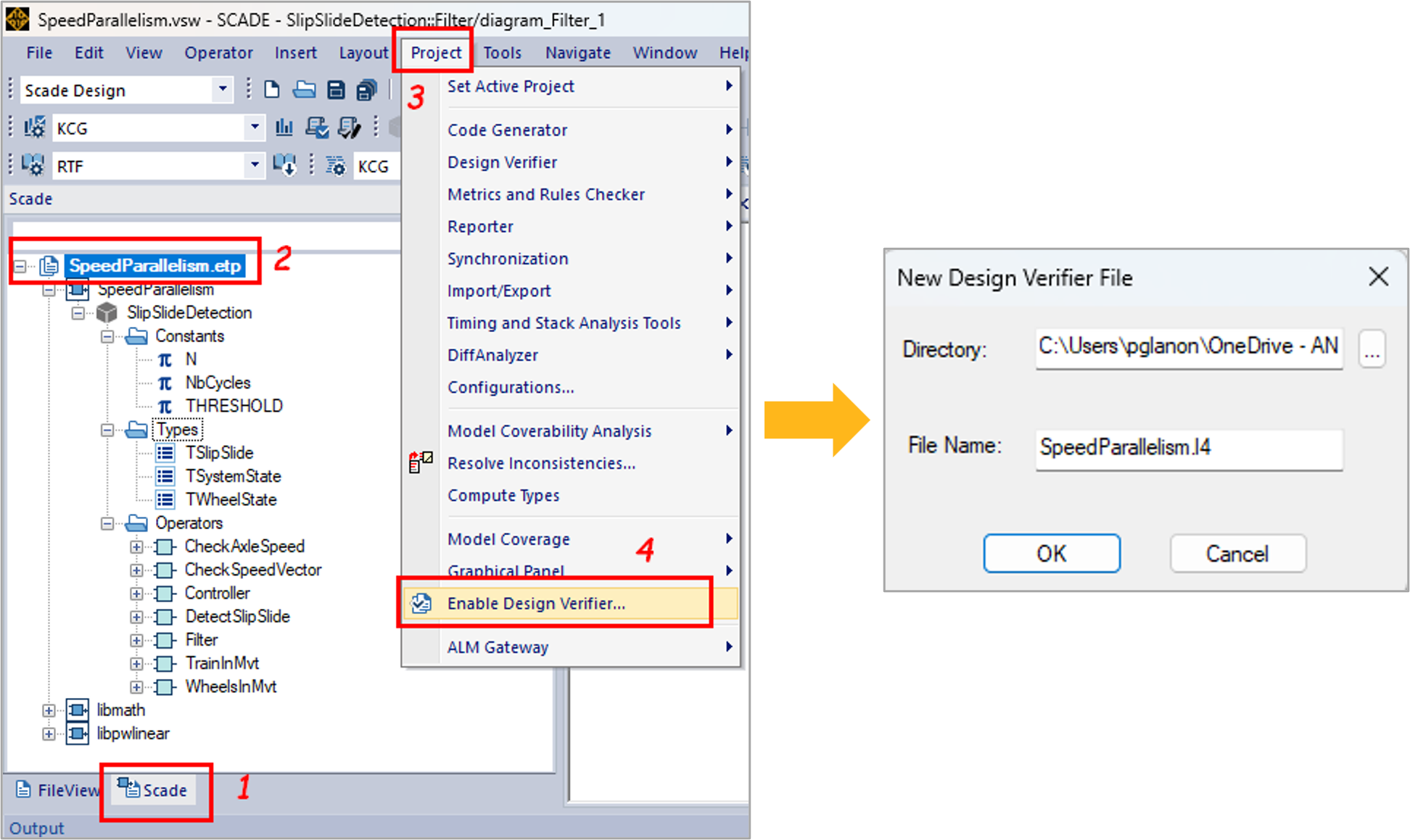
Figure 4: Enabling SCADE DV in your design projectStep 3: Formalize the verification properties in SCADE
Now that the verification properties have been defined, they can be specified in SCADE. For example, let us consider the subsequent property of the functional requirement #Req1 as specified in Table 2:
Property “On Detection”: If there is an axle whose speed is greater than the minimum speed threshold then the controller is On.
This property describes a logical proposition A => B where:
- A is the part of the proposition which loops over the axle speed vector and checks if an axle speed is greater than the minimum speed threshold.
- B is the part of the proposition which checks that the slip slide detection system is enabled.
Figure 5 illustrates the Scade description of the property “On Detection”. The blocks surrounded in yellow and red respectively describe A and B and the logical implication “=>” is described by the built-in block “implies” of the SCADE DV library “libverif”.

Figure 5: Specification of property “On Detection” in SCADEAll the properties for our application example can be defined using the same modeling principles and the built-in blocks available in the SCADE DV library. Figures 6, 7 and 8 respectively depict the Scade description of the properties “Slip Detection“, “Slide Detection” and “Parallel Speed“.

Figure 6: Specification of property “Slip Detection” in SCADE

Figure 7: Specification of property “Slide Detection” in SCADE

Figure 8: Specification of property “Parallel Speed” in SCADENote: As safety standard, recommend the separation of the design activities from the verification activities, if you have enabled SCADE DV in your design project, all the verification properties must be created in a separate package for verification.
Step 4: Specify user proof objectives
Once the verification properties are specified, you need to define proof objectives. Proof objectives can be defined in a proof harness. A proof harness is a SCADE operator used as wrapper to combine the software component under verification and the properties that shall be satisfied. Figure 9 illustrates the proof harness for our application example where the four verification properties take as input the interfaces of the slip-slide detection software component. The outputs of the properties are proof objectives which are passed to the model checker as Boolean constraints. Considering these proof objectives, the model checker will try to prove that properties are always true.
Note that in a proof harness, you can also constrain the definition domain of your software’s input interfaces to avoid considering values that are known to be unreachable in your software design. This will add an execution context to your verification and will reduce the exploration space of SCADE DV’s model checkers.
In our application example, we constrained the definition domain of the train speed, and the axle speeds to fit within the [0; 350] range.
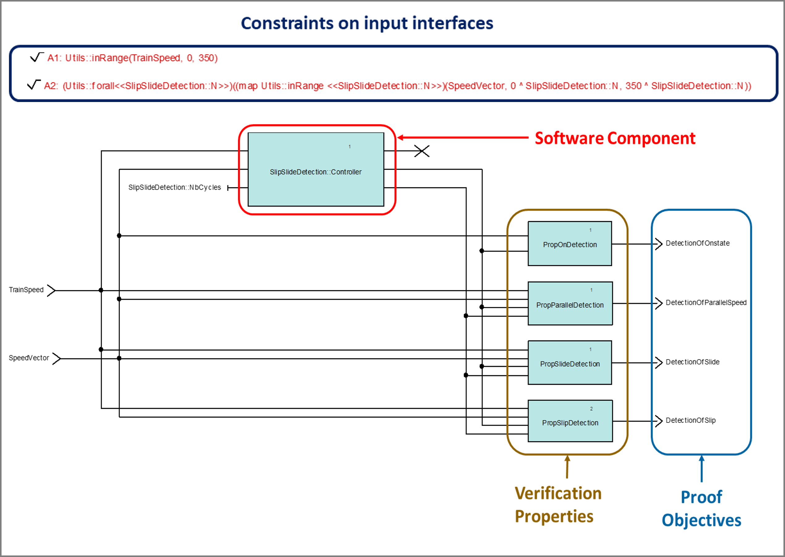
Figure 9: Proof harness for slip-slide detection softwareNow that the proof objectives have been defined, you can pass them to the model checker as shown in figure 10. For this purpose, you need to select the proof objectives from the SCADE design view and insert them as user proof objectives. Once they have been inserted, you can explore the Design verifier view to check the new proof objectives.
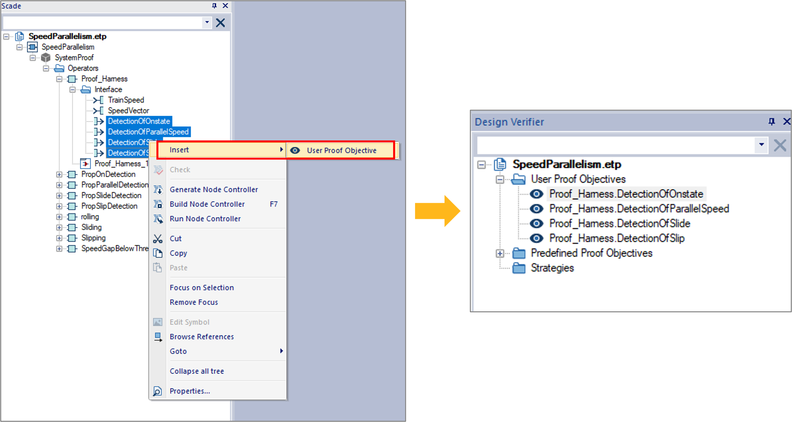
Figure 10: Pass a user proof objective to the model checkerStep 5: Specify the verification strategies
To analyze a proof objective (PO), you must associate it with a verification strategy. In SCADE DV, you can either select a set of default and configurable strategies, or you can specify a custom strategy based on Prover PSL Strategy definition syntax. A deep look into these strategies will be had in future posts. In this example, let us associate our POs with the default proof strategy as shown in Figure 11. This strategy tries to prove the validity of a property until it either succeeds or find a counter-example.
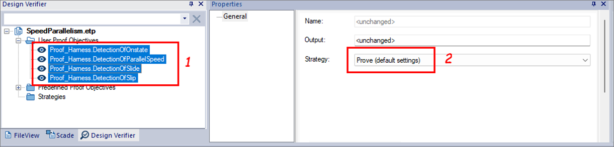
Figure 11: Applying a Strategy to a POStep 6: Launch the analysis
To run model checking, right-click on the inserted POs, then click Analyze as shown in figure 12. Once you launch the analysis, a window pops up with a progress bar that shows the status of the verification tasks. From this window you can click “Abort” to interrupt the analysis if there is any issue. Otherwise, when the analysis is completed, a Done message appears under the progress bar, and you can close the analysis window.
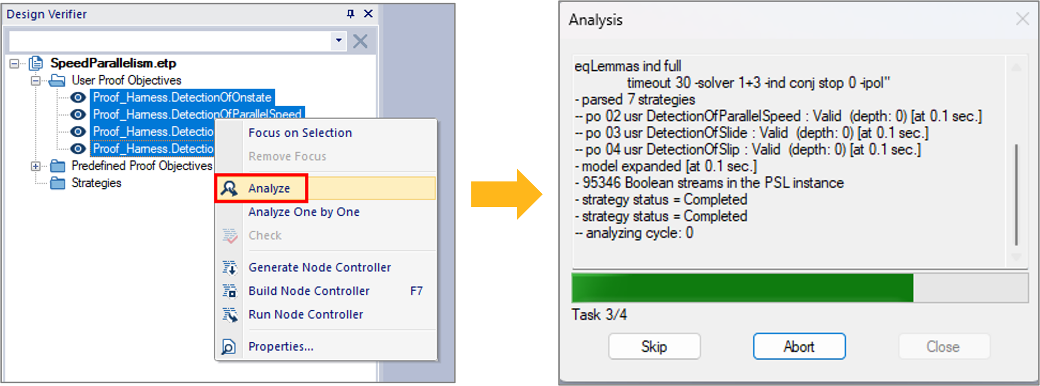
Figure 12: Launch the verification analysisStep 7: Review the results
Once the analysis is completed, results are displayed in the output browser as shown in Figure 13 where the keyword “valid” means that the verified property is always true and the keyword “falsifiable” means that the verified property can be false. In our example, the PO that verifies the activation of the slip-slide detection system is falsifiable, which means that the system might not switch to on while the train starts moving. A detailed report is also generated, which provides details on the verified PO and the verification strategy used for the analysis. Figure 14 illustrates the generated report for our application example. For falsifiable POs, the checker generates one or multiple counterexamples, that lead to the scenarios in which the verification is false.
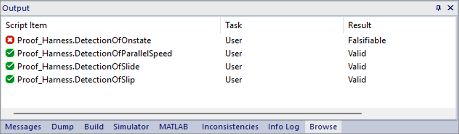
Figure 13: Using assertions in your component
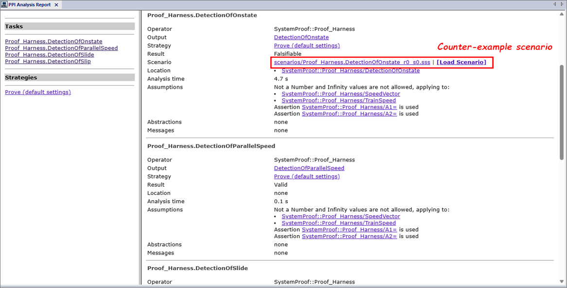
Figure 14: Generated analysis report for our application exampleFor our application example, a single counterexample is generated for the falsifiable PO. You can use the “Load Scenario” link, in Figure 14, to pinpoint the error in simulation and fix the design accordingly. But before loading the counterexamples, you first need to configure the SCADE Simulator. Figure 15 shows the configuration steps for the simulator:
- Open the configuration settings following steps 1-3.
- Select the root operator (proof harness) following steps 4 and 5.
- Select the SCADE Simulator as execution target following steps 6 and 7.
- Enable the SCADE Debugger and validate the changes following steps 8-10.
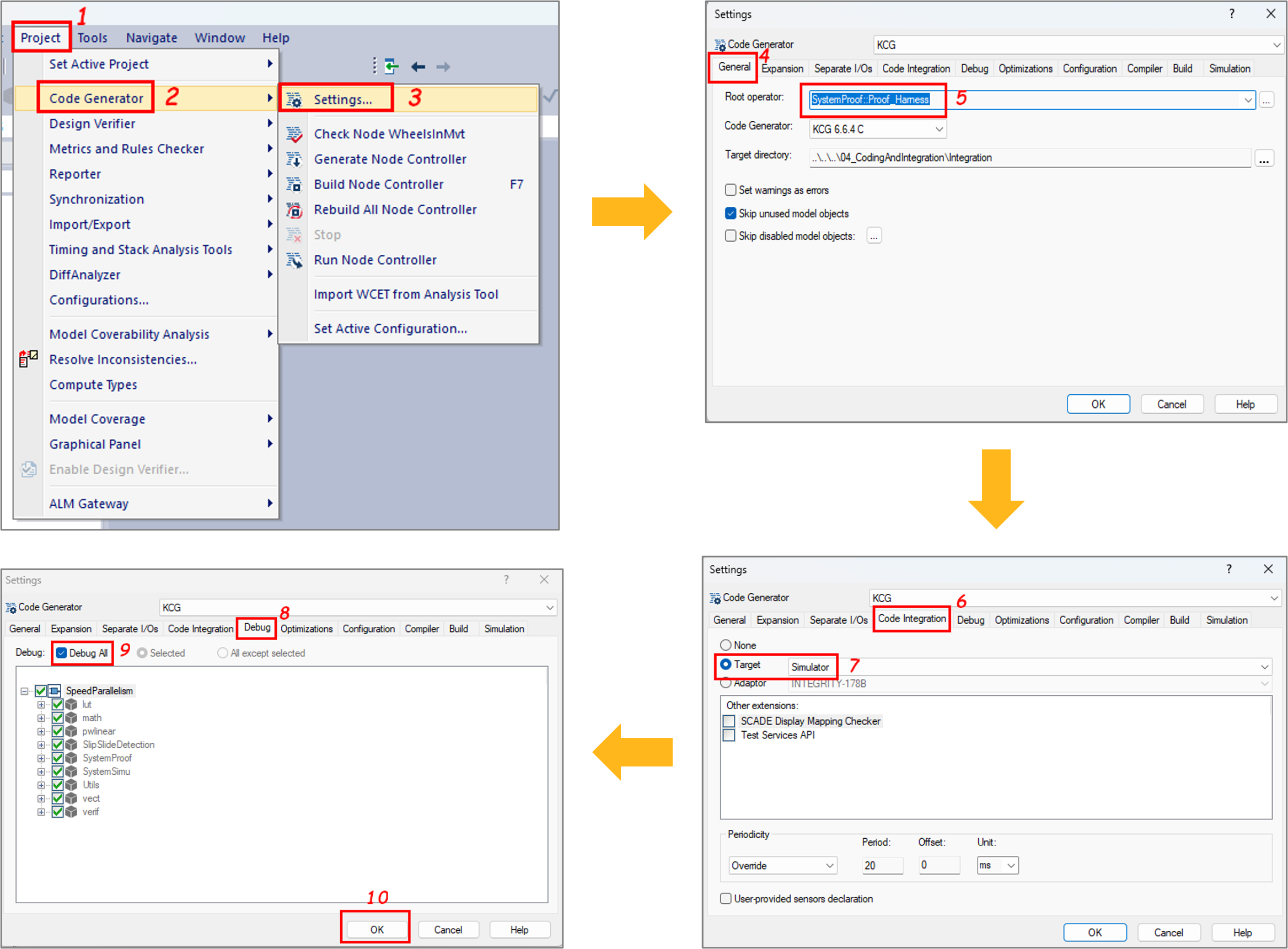
Figure 15: Configuration of the SCADE SimulatorNow that the SCADE Simulator is configured, you can simulate the falsifiable PO by loading the counterexample. As soon as you load a scenario, the SCADE simulator is launched, and you can play steps to identify the computation paths that lead to the falsification. Figure 16 shows the results of the scenario that led to a falsifiable PO for the property “On Detection“. This result clearly shows that the logical relation A=>B is falsified as there is at least an axle speed whose value is greater than the minimum speed threshold and the detection system is not activated. It means that we need to review the specification of the function that detects the train movement.
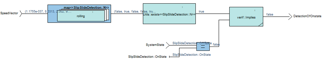
Figure 16: Simulation result with the counter-example scenario for the falsifiable PO “On detection“Figure 17 depicts the specification of the function that detects train movement. The function takes as input a vector that references the axle speeds, and it returns the system state. Considering its implementation, one can notice that the function integrates an iterator which loops over the speed vector, and it returns
trueonly if all the wheel axles have their speed greater than the minimum threshold. With regards to the property “On detection“, this implementation is incorrect as we consider a train as in movement when a least one of its axles has a speed greater than the minimum speed threshold. To fix this design error, one can replace the “AND” logic gate with an “OR” logic gate.

Figure 17: Function for the train movement detectionOnce the design error is fixed, you can run the verification again and will notice that all the properties of our slip-slide detection software are valid as shown in figure 18.
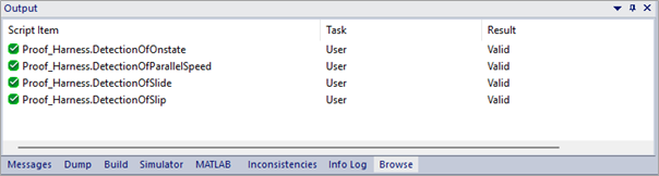
Figure 18: Final results for the train movement detectionReviewing the whole verification steps
In the following video, you can review all the steps for the verification of the properties for our slip-slide detection software.
Conclusion
In this blog, we have shown how Design Verifier, the model checker of SCADE Suite design environment can be used to verify functional and safety software requirements. In future posts, we will tackle the automation process to run the tool in batch mode, and we will dive deeply into the verification strategies implemented by the tools.
In the meantime, if you want to experiment, the model used in this article is available upon request.
If you wish to know more about how SCADE DV can improve your embedded design workflow, you may contact us from the Ansys SCADE Suite page.
About the author

Dr. Philippe Glanon (LinkedIn) is a technical expert in the design and development of Safety-Critical Embedded Systems and Software. As a senior application engineer at Ansys, he promotes model-based design solutions and he supports customers in aerospace, railways and automotive industries to achieve success through the adoption of SCADE products.
-


Introducing Ansys Electronics Desktop on Ansys Cloud
The Watch & Learn video article provides an overview of cloud computing from Electronics Desktop and details the product licenses and subscriptions to ANSYS Cloud Service that are...
How to Create a Reflector for a Center High-Mounted Stop Lamp (CHMSL)
This video article demonstrates how to create a reflector for a center high-mounted stop lamp. Optical Part design in Ansys SPEOS enables the design and validation of multiple...
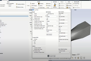
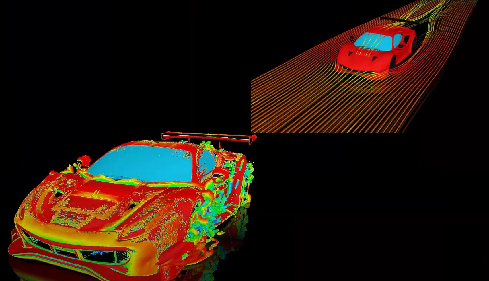
Introducing the GEKO Turbulence Model in Ansys Fluent
The GEKO (GEneralized K-Omega) turbulence model offers a flexible, robust, general-purpose approach to RANS turbulence modeling. Introducing 2 videos: Part 1 provides background information on the model and a...
Postprocessing on Ansys EnSight
This video demonstrates exporting data from Fluent in EnSight Case Gold format, and it reviews the basic postprocessing capabilities of EnSight.

- An introduction to DO-178C
- ARINC 661: the standard behind modern cockpit display systems
- Scade One – Bridging the Gap between Model-Based Design and Traditional Programming
- SCADE and STK – Satellite Attitude Control
- Scade One – An Open Model-Based Ecosystem, Ready for MBSE
- Scade One – A Visual Coding Experience
- Using the SCADE Python APIs from your favorite IDE
- Introduction to Formal Verification and SCADE Suite Design Verifier
- Efficient Development of Safe Avionics Software with DO-178C Objectives Using SCADE Suite
- How to integrate multiple SCADE models into one executable

© 2026 Copyright ANSYS, Inc. All rights reserved.
