

-
-
January 2, 2025 at 4:02 pm
 SolutionParticipant

Photo Credit: Eric Sanman @ PexelsThe avionics standard ARINC 661, developed by Aeronautical Radio, Inc. and managed by SAE ITC, is pivotal in modern Cockpit Display Systems (CDS): it enhances the efficiency, usability, and safety of aircraft cockpit interfaces.
Ansys has been an active member in the ARINC 661 standard definition committee since its inception, more than two decades ago.
In this blog post, we introduce the ARINC 661 standard: its historical context, its technical key components, its benefits and challenges, and finally its implementation.
So, let’s get started on our journey.
Historical Background
To understand the purpose of this standard, let’s go back a bit to the past.
In the 1970s, traditional cockpits in commercial and military aircraft began to be replaced by glass cockpits. This transition moved cockpit instruments from analog “steam gauges” to digital displays using LCD screens.
At first, these digital instruments were just a standalone digital replacement for the equivalent analog equipment. However, this design required adding a new computer and screen for each new application, which was not scalable to meet the growing information needs of pilots.
This need led airframers to combine many instruments into a single computer and screen, reducing pilot workload and aircraft weight. Modern cockpits now feature fewer but larger displays, such as a Primary Flight Display (PFD) and several multi-function displays. These displays are controlled by keyboards, pointing devices (like trackpads), and even touch screens.

De Havilland DHC-4 (analog instruments) vs AirBaltic Airbus A220-300 (large digital displays).
Photo credit: Miguel Cuenca @ Pexels, WikimediaThis major transition introduced several new challenges:
- Previous instruments were standalone equipment with proprietary interfaces, but now we have a system that interacts with multiple sub-systems.
- Any change in the display could impact different sub-systems and vice versa, necessitating the certification of the entire system regardless of where the changes occur.
- These interconnections between equipment make it difficult to switch equipment or reuse display elements if the software architecture changes.
- Managing the various requests from sub-systems and controllers to determine what should be displayed, where, and how, without blocking the entire system.
- Managing concurrent demands for different functions between pilots during flight operations (e.g. the pilot wants to open Menu A while the co-pilot wants to open Menu B).
The avionics industry needed a standardization of the display in the cockpit. Aeronautical Radio, Inc. (ARINC) provided a solution with the ARINC 661 standard.
Key Elements of ARINC 661
ARINC 661 is a standard for defining interactive avionics display systems. Its intent is to minimize the effort and cost of improving cockpits as technology evolves (new avionics systems, new features on existing systems, new hardware in the cockpit). Widely adopted across the aerospace industry, it promotes interoperability between avionic systems and simplifies vendor integration.
It provides the following advantages:
- Efficient Data Combination: Combines data and requests from different subsystems with safety mechanisms.
- Agility for Updates: Facilitates changes and updates in the system, including hardware changes.
- Standardized Protocol: Provides a non-proprietary protocol for data exchange between the main system and subsystems.
To do so, the standard defines the following key elements:
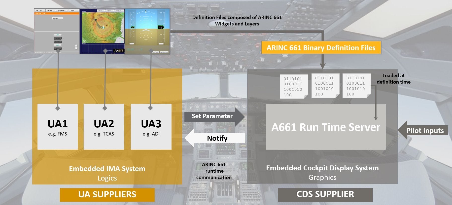
- For efficient data combination: a client-server architecture with a centralized server (Cockpit Display System or CDS) and multiple clients (User Applications or UAs). The server manages interaction with crew controls and graphics hardware, while each UA handles specific aircraft systems (e.g., Primary Flight Display, Flight Management System, Fuel Management, Traffic Collision Avoidance System, etc.).
- For agility: a predefined set of HMI (Human-Machine Interface) widgets, ranging from basic graphical primitives to navigation maps. The UAs can have an associated graphical display using instantiations of these widgets in a Definition File (DF).
- For standardized protocol: a runtime communication protocol between the server and User Applications for efficient data exchange and user event handling (e.g. button pressed, cursor clicked, or touch/gestures).
The following relationships exist between the different elements:
- CDS (Cockpit Display System): Acts as an aircraft-embedded server that implements widget behavior and display, as well as other services such as network communication, managing pilot inputs, and loading Definition Files (DFs).
- UAs (User Applications): Implements the logic of the subsystems.
- DFs (Definition Files): Represents the display controlled by the UAs. They are loaded into the server upon launch.
- ARINC 661 Runtime Communication Protocol: Defines the protocol for bi-directional data exchange between the UAs and the CDS (setting parameters and getting notifications).
ARINC 661 Widgets
Widgets are the core elements of the ARINC 661 Standard and have been enriched across different versions to meet the evolving needs of the industry. As of 2024, there are 119 widgets defined in the latest version of the standard (Supplement 9).
The standard defines several overlapping categories of widgets:
- Container: Widgets to group of several child widgets together. Used for example to create menus, tabs, popups, make children blink, or scale children to fit given dimensions.
- Graphical Representation: Widgets with a graphical representation, comprising more than half of the widgets. These range from basic graphical elements (e.g., shapes or text) to more complex ones (e.g., buttons, panels, map elements).
- Text String: “Graphical Representation” widgets that can display text. This includes pure text, numeric value displays, buttons, menus, scroll lists, editable fields, etc.
- Interactive: Widgets that users can interact with or that receive events. Mostly graphical representation widgets (e.g., buttons, editable fields) with exceptions like areas to record pointer positions, scroll wheel movements, or keyboard key presses.
- Utility: Widgets that are not containers, interactive, or graphical representations. Used for example to scale values, change pointer focus, animate other widgets, or display data from a video stream.
- Map Management: Widgets for displaying horizontal and vertical maps (typically for Navigation Display applications), including coordinate and projection systems, elements to display, and map backgrounds.
- 3D Map Management: Widgets for displaying 3D maps (introduced in Supplement 8 in 2020), including coordinate systems, camera and lighting management, and elements to display.
Widgets have an interface that contains the following elements:
- Definition Parameters: parameters that are set during the instantiation and cannot be changed.
- Runtime Parameters: parameters that can be changed dynamically by a request from the UA or by other widgets (usually overlapping with Definition Parameters).
- Events: notifications sent by the widget to the UA (e.g. a button has been pressed or the 3rd choice has been selected).
Widgets have an interface that contains the following elements:
- Definition Parameters: Static parameters set when the DF is loaded.
- Runtime Parameters: Dynamic parameters that can be changed by a request from the UA or by other widgets (these parameters usually overlap with Definition Parameters).
- Events: Notifications sent by the widget to the UA (e.g., a button press or a selection of a choice among a list).
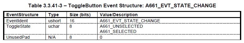
Example of ToggleButton Widget
Let’s have a look at a simple Widget: the ToggleButton. This widget has two states that change when we press the button (selected and unselected) and it has some text for the label of the button.
This widget could have a graphical representation like this one:

The parameters of this widget are the following, as described in the ARINC 661 Standard:
Definition and Runtime Parameters of the widget ToggleButton
Parameter
Description
Definition
Runtime
WidgetType
Constant value: A661_TOGGLE_BUTTON
Yes
No
WidgetIdent
Identifier of the widget (an integer)
Yes
No
ParentIdent
Identifier of the parent (0 if put at root level)
Yes
No
Enable
Ability to be interactive
Yes
Yes
Visible
Possibility to hide the widget
Yes
Yes
PosX, PosY
Position of the lower-left hand corner of the button
Yes
Yes
SizeX, SizeY
Width and height of the button
Yes
Yes
StyleSet
Identifier of a Styleset (i.e. predefined graphical characteristics) set in the CDS
Yes
Yes
NextFocusedWidget
Identifier of another widget on which to move the focus after a given key is pressed or, if AutomaticFocusMotion is true, after this button is triggered
Yes
Yes
MaxStringLength
Maximum size (in bytes) of the label text (including the ending character, so “Hello” counts as 6)
Yes
No
ToggleState
State of the widget: either selected or unselected
Yes
Yes
AlternateFlag
Whether to have a different label when the button is selected (set in AlternateLabelString)
Yes
Yes
AutomaticFocusMotion
Automatically move the focus to the widget set in NextFocusedWidget
Yes
Yes
Alignment
Horizontal alignment of the text (left, center, right)
Yes
Yes
LabelString
Label of the button when unselected or if AlternateFlag is false
Yes
Yes
AlternateLabelString
Label of the button when selected if AlternateFlag is true
Yes
Yes
EntryValidation
Runtime parameter required to validate the selection of the button if Enable is set to “True with Validation”
No
Yes
The events are described in the following table extracted from the standard:
Definition File (DF)
A Definition File describes a page with instantiation of widgets organized in one or several layers. The Standard specifies two file formats for DFs:
- A binary format, that is meant to be loaded by the CDS
- An XML format, intended to provide a convenient interchange format between ARINC 661 tools
A DF binary file has the following structure for its data:
# Header with version of ARINC 661 used

# Optional data to define elements:
#…	character encoding, symbols, pictures, or animation laws

# One or more blocks for layers which are composed as follows:
#…	start of layer block
#…	one or more blocks for widget instantiation (definition parameters only)
#…	end of layer block

# Footer
If we create a simple display with a single layer containing a single ToggleButton, we have a DF with 5 parts:
- Header
- Start of the Layer Block
- Block for the Toggle Button to instance its Definition Parameters (as described above)
- End of the Layer Block
- Footer
The content of the file would look like this (the comments after “#” character have been added for improving clarity):
# 1. Header
# => We use ARINC 661 Supplement 9 and we define layers for Application #1
A661 # A661_DF_MAGIC_NUMBER
01 # LibraryVersion
09 # SuppVersion
0001 # AppliIdent (Application #1)
0000 # Size of the OEM free data

# 2. Beginning of block to create a Layer
# => We create a Layer with ID = 1
A0 # A661_BEGIN_LAYER_BLOCK
01 # LayerIdent
0000 # Context Number
00000058 # Size of block for the layer (88 bytes)

# 3. Block to create a Widget (ToggleButton)
# => We create a ToggleButton with ID = 1 with no parent
# ... at position (1000, 1000) with size (3000, 800)
CA01 # A661_CMD_CREATE
004C # Size of block for the widget (76 bytes)
A340 # WidgetType (A661_TOGGLE_BUTTON)
0001 # WidgetIdent
0000 # ParentIdent
01 # Enable (A661_TRUE)
01 # Visible (A661_TRUE)
000003E8 # PosX (1000)
000003E8 # PosY (1000)
00000BB8 # SizeX (3000)
00000320 # SizeY (800)
006E # StyleSet (110)
0000 # NextFocusedWidget (0 = no next focused widget)
0020 # MaxStringLength (32)
00 # ToggleState (A661_UNSELECTED)
01 # AlternateFlag (A661_TRUE)
00 # AutomaticFocusMotion (A661_FALSE)
13 # Alignment (A661_LEFT)
0000 # UnusedPad
4C616265 # LabelString (Labe)
6C537472 # (lStr)
696E6700 # (ing\x00)
416C7465 # AlternateLabelString (Alte)
726E6174 # (rnat)
654C6162 # (eLab)
656C5374 # (elSt)
72696E67 # (ring)
00 # (\x00)
000000 # UnusedPad

# 4. End of block to create a Layer
C0 # A661_END_LAYER_BLOCK
000000 # UnusedPad

# 5. Footer
E0 # A661_DF_FOOTER
000000 # UnusedPad
By examining this file, we can observe two things:
- The size of the data for a layer and a widget is specified at the beginning of the block, allowing the Server to determine the necessary memory allocation for their creation.
- Padding (“UnusedPad”) is used to ensure correct alignment of blocks on 32 bits.
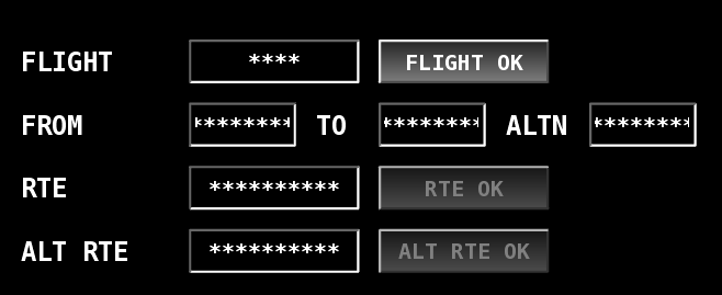
Example of Widget Instantiation
Below is a simple example of an instantiation of several widgets to mimic the entry of flight information: it uses the following widgets:
- Display of text (“Label” widget)
- Editable fields to enter information (“EditBoxText” widget)
- Single-state buttons to valid the value (“PushButtons” widget)
Benefits and Challenges
As previously discussed, the ARINC 661 Standard provides the following key benefits:
- Easy Upgrade of UAs: The airframer can replace aging UAs with new ones without having to re-certify the whole cockpit.
- Standardization and Compatibility: A consistent communication protocol and widget interface simplifies integration, maintenance, and upgrades while lowering development costs. You can upgrade a legacy server with no impact on User Applications and reuse legacy User Applications with minimal modifications.
- Safety and Reliability: Designed for safety-critical systems, the protocol can robustly handle requests and errors, including concurrent requests.
- Enhanced User Interface: The widgets enable CDS developers and UA providers to create intuitive and user-friendly cockpit displays with consistent look and feel, improving pilot usability and awareness. The standard is continuously evolving to provide ongoing interface improvements.
- Reduced Time to Market and Flexibility: Efficient handling of the complete program lifecycle from early prototyping to certification, with clear definition and separation of responsibilities between parties. The flexible approach also makes it easier to handle late modifications.
More specifically, for UA Providers, the ARINC 661 Standard offers additional advantages:
- Look & Feel Independence: Changes in the CDS ARINC 661 server’s look and feel do not impact UA certification.
- UA Reusability: UAs can be reused on any ARINC 661 compliant aircraft.
- Verification and Validation: Clear separation between logic and graphics allows UA logic to be verified independently.
- Standardization Benefits: No need to learn and purchase new protocols or tools for different aircraft, as a public standard allows the use of COTS tools and methods.
However, the adoption of the ARINC 661 Standard faces several challenges:
- Cost of Implementation: Designing a CDS is time-consuming due to the number of widgets to implement (more than a hundred in Supplement 9), especially in a DO-178C / DO-254 certified project.
- Steep Learning Curve: The complex structure and details of the standard require a deep understanding, which can delay adoption and project deadlines.
- Interoperability Issues: Combining ARINC 661 applications with non-ARINC 661 applications can be challenging.
Implementation
Implementation of CDS
The implementation of a Cockpit Display System (CDS) requires many complex features, including:
- Widget Behavior and Graphical Representation: Implementing and displaying widget behavior, which is the most time-consuming task.
- Widget Management and Interaction: Managing the widgets, their interactions with each other, and their priorities.
- Management of Multiple UAs: Managing priority and scheduling communications to avoid conflicts.
- Error Management and Robustness: Ensuring the system can handle errors gracefully, report errors, and maintain robustness.
- Display Management: Handling the graphical display of widgets, including drawing priorities, multiple displays, and multiple windows.
- Loading Definition Files (DFs): Loading DFs and encoding/decoding data exchanged over the Runtime Protocol.
- Network Communication: Handling network communication.
- Crew Control Management: Managing crew controls such as trackballs, buttons, keyboards, and touch screens
- Additional Features: Implementing various other necessary functionalities.
All these features must be developed with a focus on robustness, performance (including CPU, GPU, and memory usage), fast graphical rendering, low latency for user interactions and data processing, and compatibility with the OS and hardware of the target embedded system. Additionally, the CDS project typically needs to be certified under DO-178C.
The development activities for a hand-coded CDS project certified for DO-178C with 94 widgets are estimated to require almost 1,000 person-months, including testing and verification activities. With ARINC 661 Supplement 9 specifying 119 widgets and this number continually increasing, the workload for future projects will only grow. The cost could be reduced by using a model-based approach with an estimated gain of at least 30%.
As the testing activities in a CDS project represent 30-40% of the total cost, the need for automated testing in the development of ARINC 661 Widgets cannot be overstated. We will talk more about this topic in a dedicated blog series.
Implementation of DFs
To create a DF, three methods are possible:
- Writing the DF by hand: This method is tedious, error-prone, lacks consistency, and is difficult to review and maintain.
- Creating a DF programmatically: While suitable for quick prototyping, this method becomes impractical for industry-sized DFs containing hundreds or thousands of widgets.
- Using a Model-Based approach with a DF generation tool: This is the most suitable method, as it facilitates easier creation, collaboration, consistency checks, maintenance, and graphical visualization during modeling if the tool includes a CDS runtime. This method is especially advantageous for achieving DO-178C certification.
Implementation of UAs
A UA consists of two main components:
- The code for the logic part.
- The code for the ARINC 661 Runtime Protocol, which handles network communication and encoding/decoding of data.
Since UAs are closely tied to their associated DFs, using a Model-based approach for developing DFs makes it more suitable to also use a Model-based approach for the logic part, ensuring consistency with the DF interface.
Implementation with Ansys SCADE
The SCADE Solutions for ARINC 661 Compliant Systems is a comprehensive tool suite for creating and generating embedded software for ARINC 661 compliant Cockpit Display Systems (CDS) and User Applications (UA), together with the associated code and Definition File (DF) generators.
It uses a Model-Based approach to boost implementation efficiency while ensuring data consistency, safety, and reliability.
It provides the following capabilities:
- UA Display Modeler (DF): Uses SCADE Display ARINC 661 Advanced Modeler to create ARINC 661 pages as models, coupled with UA application logic, and completed by UA DF Generator for producing standardized Definition Files (binary and XML).
- UA Logic Modeler: Uses SCADE Suite Advanced Modeler to create UA behavioral logic, SCADE Suite KCG code generator for application code, and SCADE Suite UA Adaptor for ARINC 661 to automatically generate the communication code between UA and DF in the ARINC 661 Server.
- SCADE Widget Library: Customizable widget models (look and behavior) built with SCADE Suite & SCADE Display models, using the respective KCG qualified code generators. As of 2024, it includes 94 ARINC 661 widgets up to Supplement 9 to bootstrap the development of an ARINC 661 Widget Library.
- SCADE Server Creator: Generates source code of the ARINC 661 Server from configuration files and Widgets Library.
- Test, Documentation & Traceability Baseline: Each widget comes with test cases (using the ARINC 661 Test Automation Framework), requirement documents, and traceability matrices.
Moreover, we have the following additional features:
- ARINC 661 Extension and Styleset Mechanisms: Fully implemented.
- FACE™ Technical Standard: Both ARINC 661 Server and UA generated from SCADE solutions can be aligned with this standard.
Explore Further
This blog post provides a brief introduction to ARINC 661 standard and the benefits it provides for modern avionics display systems for Cockpits.
A coming blog series will showcase how to perform automatic testing of ARINC 661 Widgets.
If you’d like to learn more about Ansys SCADE Solutions for ARINC 661 Compliant Systems, we’d love to hear from you! Get in touch on our product page.
About the author

Jean-François Thuong (LinkedIn) is a Software Validation Manager at Ansys. He excels in software development, testing, and team management. His areas of expertise include the SCADE product, with a particular focus on Scade One. He is fluent in French, English and Chinese.
-


Introducing Ansys Electronics Desktop on Ansys Cloud
The Watch & Learn video article provides an overview of cloud computing from Electronics Desktop and details the product licenses and subscriptions to ANSYS Cloud Service that are...
How to Create a Reflector for a Center High-Mounted Stop Lamp (CHMSL)
This video article demonstrates how to create a reflector for a center high-mounted stop lamp. Optical Part design in Ansys SPEOS enables the design and validation of multiple...
Introducing the GEKO Turbulence Model in Ansys Fluent
The GEKO (GEneralized K-Omega) turbulence model offers a flexible, robust, general-purpose approach to RANS turbulence modeling. Introducing 2 videos: Part 1 provides background information on the model and a...
Postprocessing on Ansys EnSight
This video demonstrates exporting data from Fluent in EnSight Case Gold format, and it reviews the basic postprocessing capabilities of EnSight.

- An introduction to DO-178C
- ARINC 661: the standard behind modern cockpit display systems
- Scade One – Bridging the Gap between Model-Based Design and Traditional Programming
- SCADE and STK – Satellite Attitude Control
- Scade One – An Open Model-Based Ecosystem, Ready for MBSE
- Scade One – A Visual Coding Experience
- Introduction to Formal Verification and SCADE Suite Design Verifier
- Using the SCADE Python APIs from your favorite IDE
- Efficient Development of Safe Avionics Software with DO-178C Objectives Using SCADE Suite
- An introduction to space software standards ECSS-E-ST-40 and ECSS-Q-ST-80C

© 2026 Copyright ANSYS, Inc. All rights reserved.

.jpg)