Ansys Assistant will be unavailable on the Learning Forum starting January 30. An upgraded version is coming soon. We apologize for any inconvenience and appreciate your patience. Stay tuned for updates.
Ansys Innovation Courses

Ansys Innovation Courses

Provide feedback or ask questions related to the Ansys Innovation Courses content.

Problem in assigning the material orientation

    • akshay.kalgutkar
      Subscriber

      Hi everyone,

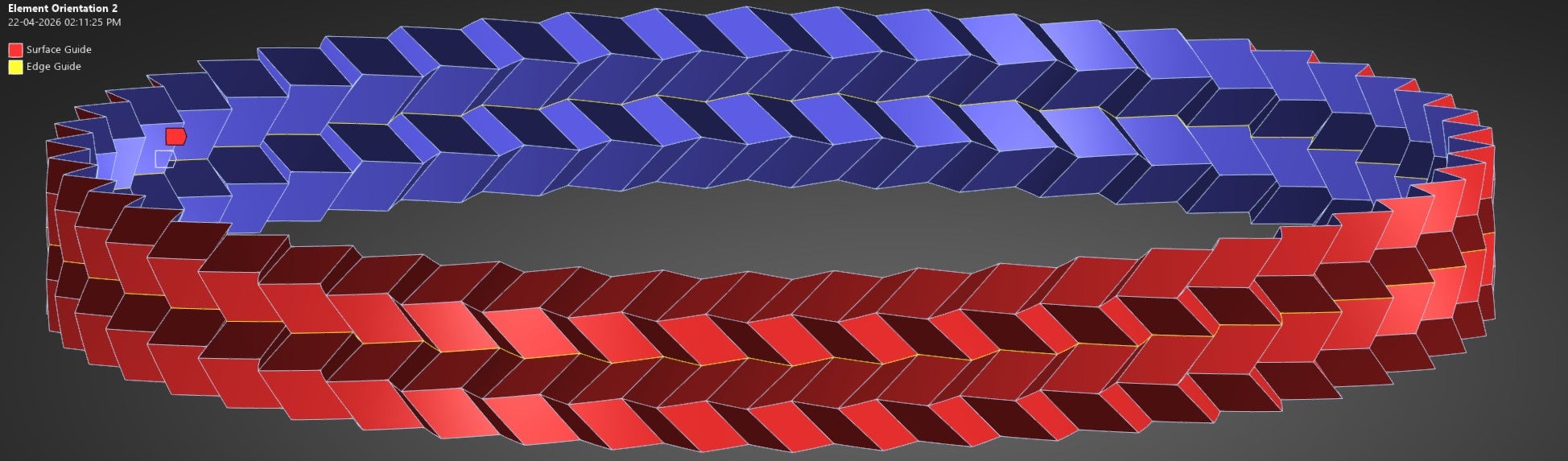
      I am currently studying the crushing performance of a Miura origami cylinder and encountering an issue with maintaining consistent material orientation across a single face.

      I am using the element orientation feature in LS-DYNA (Workbench), specifically the surface and edge guide option. In my setup:

      • The shell surface is scoped to define the z-axis (surface normal).
      • A circumferential edge is selected to define the x-axis.

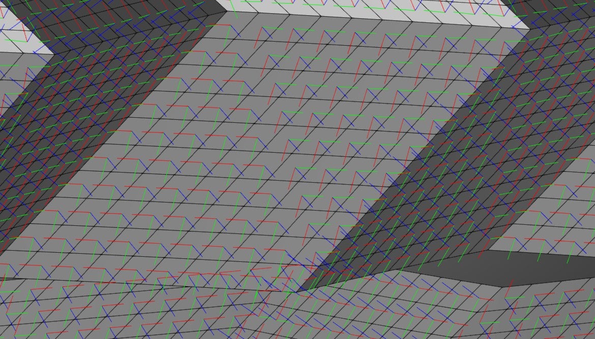
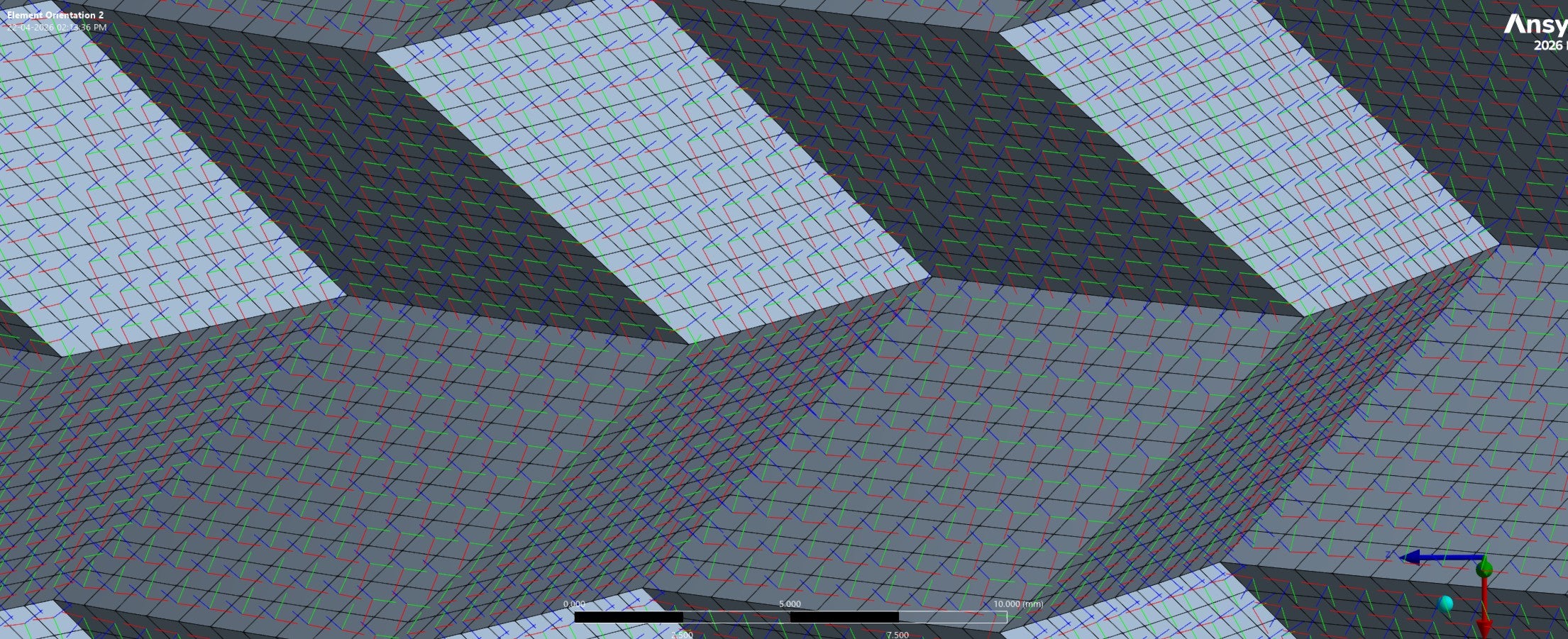
      However, after generating the orientation, I observe an inconsistency:

      • For some elements, the x-axis aligns correctly with the guided edge.
      • For others, the orientation appears rotated by 90°, such that the y-axis aligns with the same edge.

      This mismatch follows a diagonal pattern across the face (as shown in the figure) and occurs consistently on all faces, regardless of their orientation in the Miura geometry.

      I would appreciate any guidance on:

      • Why this alternating orientation is occurring, and
      • How to enforce a consistent local coordinate system across all elements on a face.

      Thank you in advance for your help.


    • mjmiddle
      Ansys Employee

      The element orientation can align directions consistently across a smooth, continuous surface. This is a piecewise linear surface. In addition, when you select a guide edge, there is no circumferential edge (not circular). These are straight edges that are not continuous at connections, so you have selected either one straight segment or many edges around the circumference. But it cannot be known exactly what you want for any of the other flat face segments that do not have your selected edges as a boundary edge on each face. I suggest you align to a coordinate system rather than "surface and edge guide." Set up a cylindrical coordinate system first at the center of this whole structure with Y axis going around this whole structure.

Viewing 1 reply thread
  • You must be logged in to reply to this topic.
[bingo_chatbox]