TAGGED: 3d-simulation, computational-fluid
-
-
July 8, 2024 at 12:00 pm
nikos_mech
SubscriberHi to the Ansys team,
As a mechanical engineer, with a basic knowledge in Ansys Fluent, I have a project (thesis) related with Natural Ventilation in Buildings.
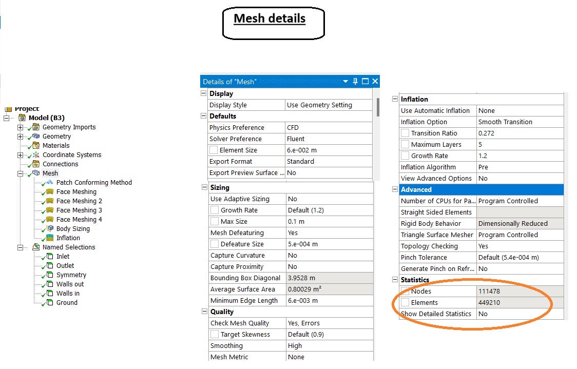
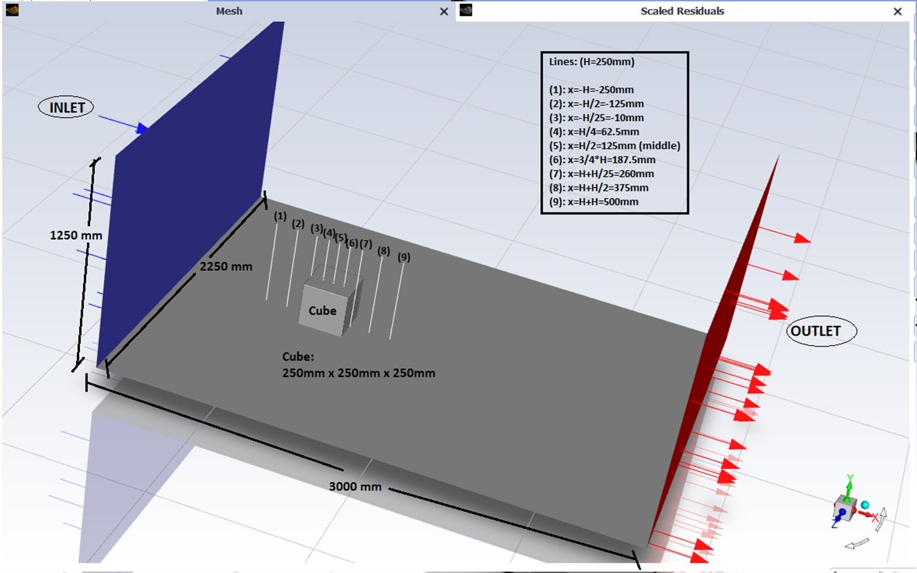
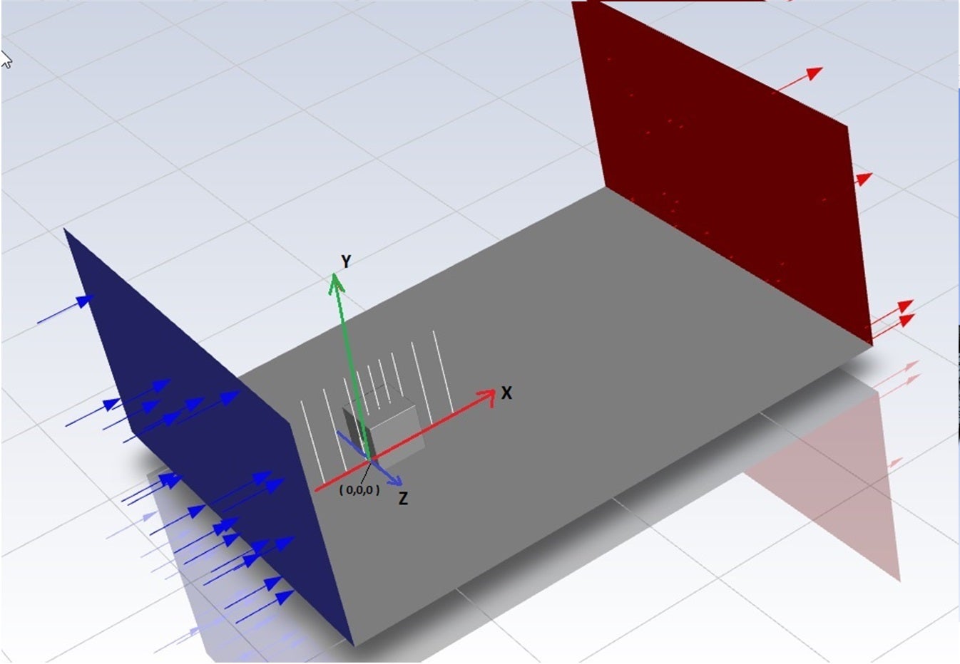
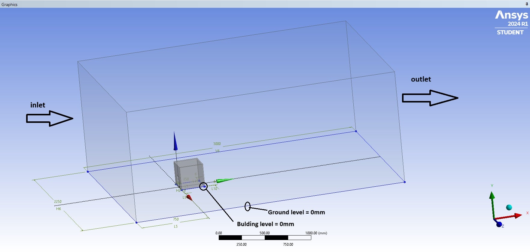
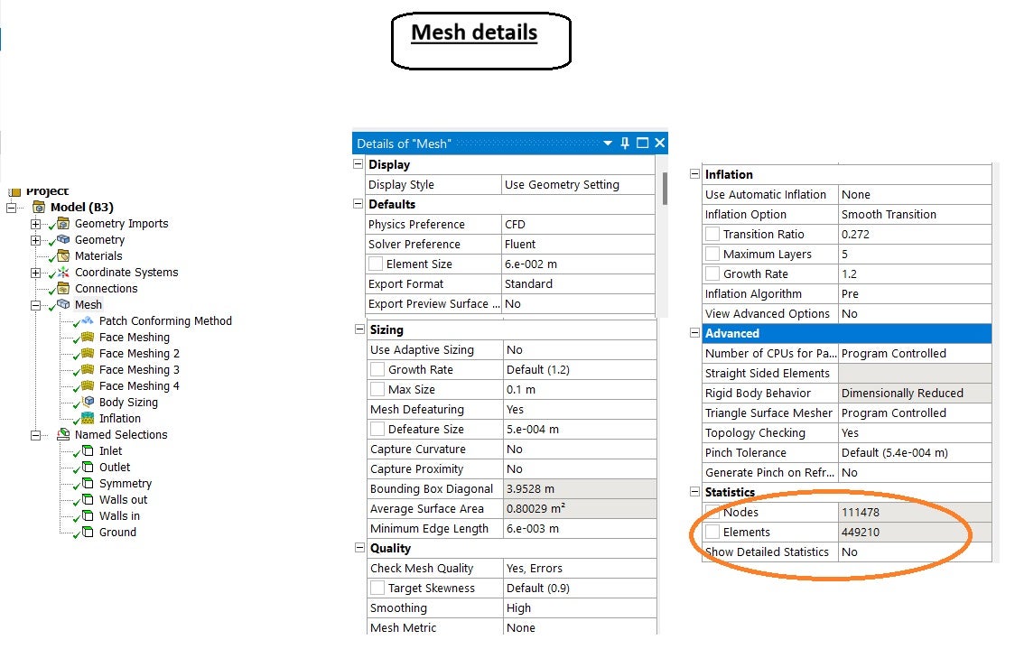
In the attached jpeg images you will find the basic information of geometry and mesh.
Other useful data:
Ø Ansys version: 2024 R1
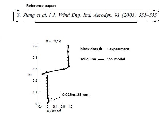
Ø The reference paper I try to follow is the "Yi Jiang, Donald Alexander et.al. (2003), Natural Ventilation in Buildings…"
Ø In the inlet I import a Ux velocity profile taken from the reference paperØ The mathematical model is k-ε STD and RNG Ø Time: Steady
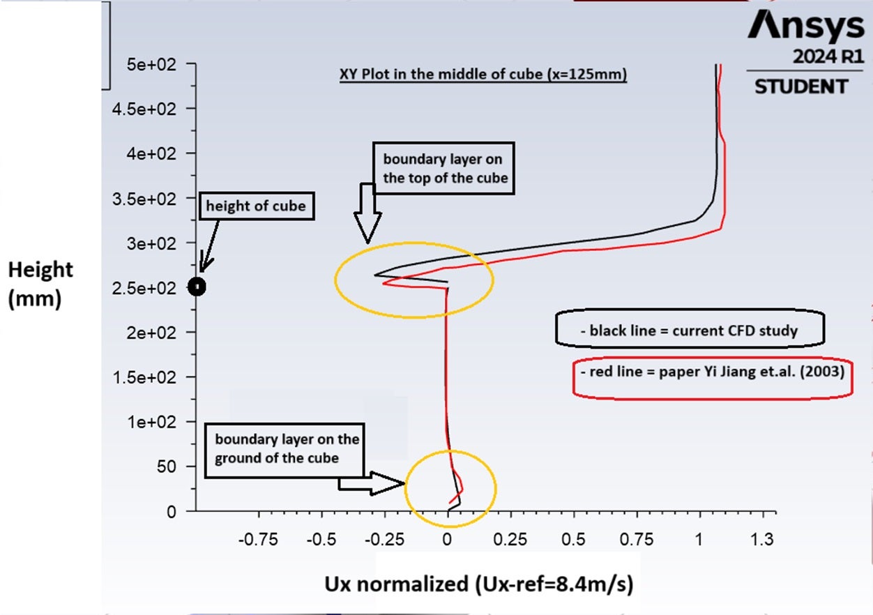
Ø Uref = 8.4m/secA major issue I face is the VELOCITY XY plot (Ux-normalized) divergence between my CFD results and the paper's results (see the attached XY plot), especially in the boundary layers.
Also, I think the mesh isn’t the best it can be.
My final goals/targets are:
- mesh independence test
- implementation of other models (k-ω and Spalart-Almaras) based on the best meshCould you give some advises in order to optimize the mesh and get better results??
If there is any other data that you need for this project please tell me to provide more.
Thank you in advanced
Nikos -
July 9, 2024 at 12:42 pm
Rob
Forum ModeratorWhat is ground level in the study? There is a fairly constant offset that also looks to be present in the lowest (height) position.
-
July 10, 2024 at 5:45 am
-
-
July 10, 2024 at 9:28 am
Rob
Forum ModeratorOK, so why does the experimental data stop just above the ground? The fact there's a vertical offset may suggest that both sets of data are correct but that there's a reference height or similar that needs to be checked.
-
July 14, 2024 at 1:42 pm
-
-
July 14, 2024 at 2:18 pm
nikos_mech
SubscriberSo, how can I soften the diference/divergence between my curve and the reference paper’s curve, especialy in the boundary layers??
is only a matter of mesh? could you suggest some optimizing mesh techniques?
or something else that needs to be checked?
Below I repost the mesh details.
Thank you for your technical support !
-
July 15, 2024 at 9:15 am
Rob
Forum ModeratorIf it's mesh related (very possibly) use inflation to give you a more resolved boundary layer. If you inflate off the block too you can probably have a "thick" inflation layer. However, you also need to ensure the streamwise mesh resolution is good near the block to capture separation.
Next up is the turbulence model. RNG k-e should be fairly good, but you may need to review the k-w variants. Fluent didn't have a k-w model in 2003, or if it did it would have been fairly new.
Finally, most wind boundary profiles assume a reference height of around 10m. So at very low level care is needed to account for surface effects - ie trees, bushes etc. I assume those aren't in the experiment?
-
July 15, 2024 at 11:23 am
nikos_mech
SubscriberThat's right...my cfd case doesn't have trees, bushes etc.
I have already used inflation and some times it gives me errors.
I'll do extra simulations and i'll send you feedback.
-
July 20, 2024 at 9:25 am
nikos_mech
SubscriberHi Rob,
By applying Iflation, it gives me the next error “Inflation created stairstep mesh at some locations”.
How do I overcome this issue ?
Can I ignore this error and keep going on with the simulation??
-
July 22, 2024 at 9:59 am
Rob
Forum ModeratorThat's a warning rather than an error. If the mesh quality is good (note, that's cell quality and mesh resolution) then you can usually ignore it. If you search for "stairstep" on here you'll almost certainly find other threads as I'm sure I've answered similar questions before.
-
- The topic ‘Natural Ventilation in Buildings_Mesh & XY Plots’ is closed to new replies.


-
2793
-
965
-
851
-
599
-
591

© 2025 Copyright ANSYS, Inc. All rights reserved.

