TAGGED: aqwa, hydrodynamic-response
-
-
December 30, 2024 at 7:04 pmoe23m012Subscriber
I am working on modeling a Split Hopper Barge in ANSYS for my thesis project and am encountering several issues. Below is a detailed description of my setup and the problems I am facing:
Model Setup:
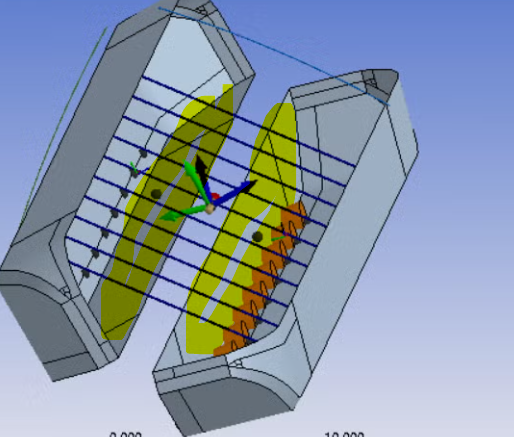
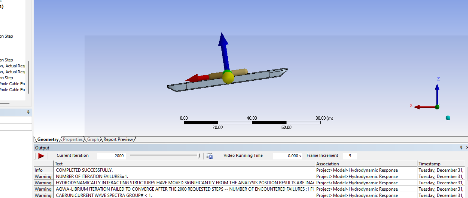
- I have created two joints on the deck: one hinge joint and one universal joint. This setup was intended to avoid redundancy. The gap between the two hulls is 180 mm, as shown in the attached diagram.
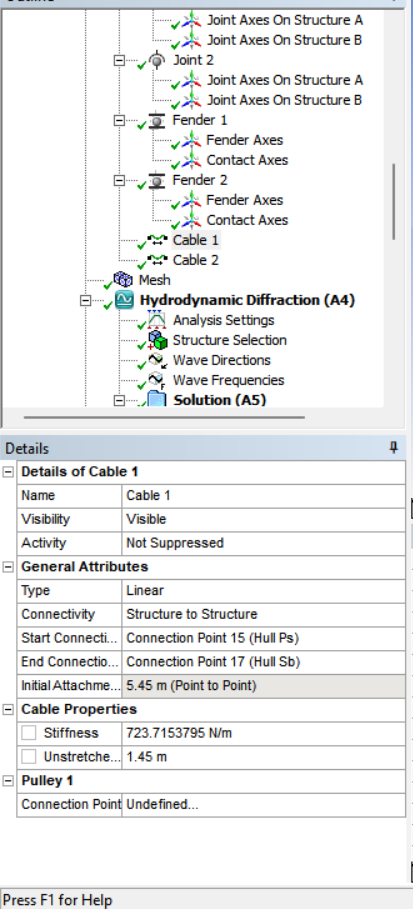
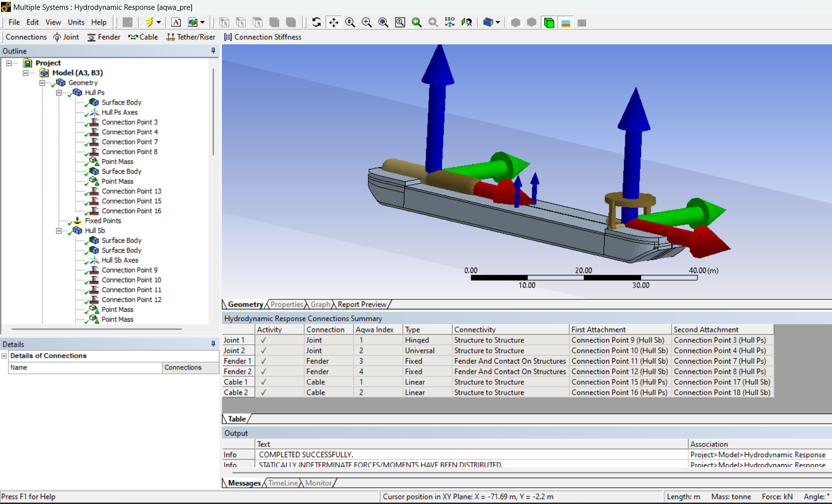
To simulate the hydraulic cylinder, I used two cables with initial tension placed below each joint. The initial tension in the cables was determined based on static force calculations.
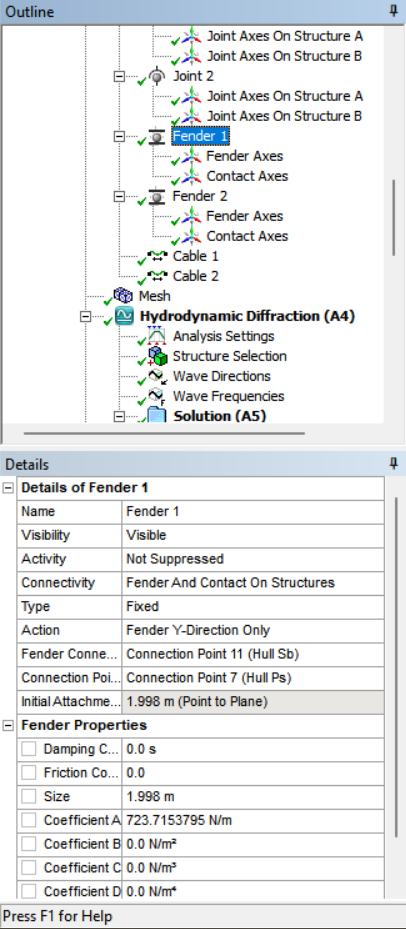
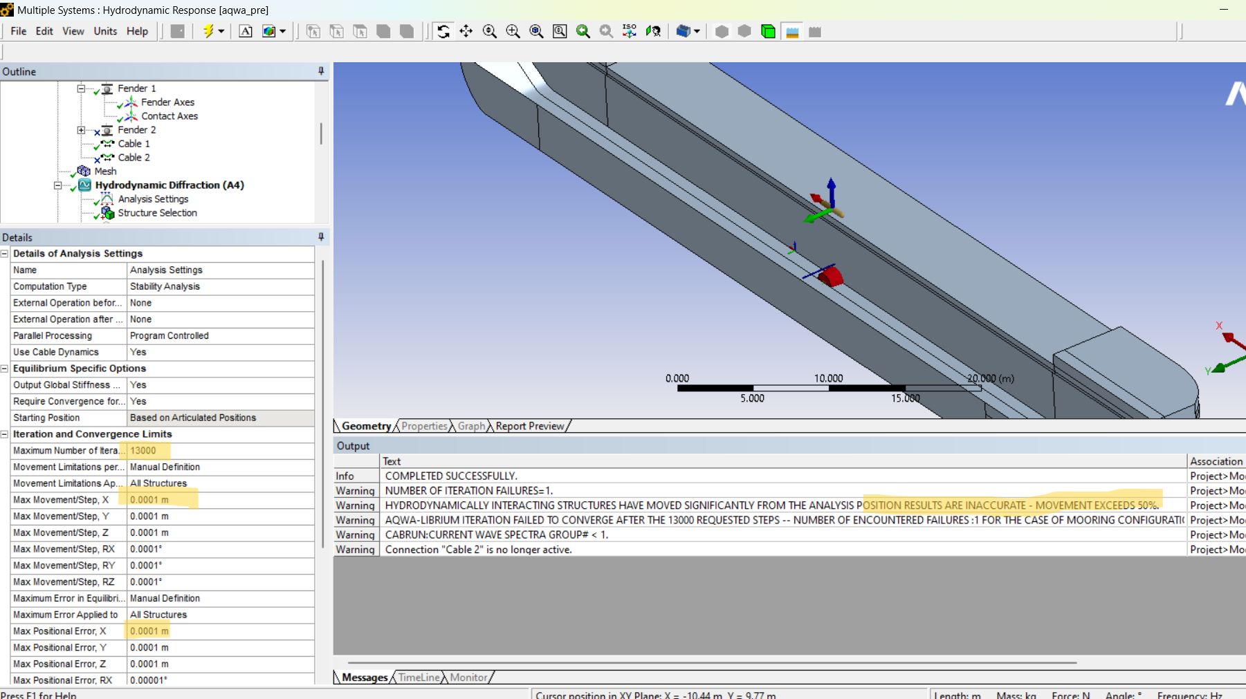
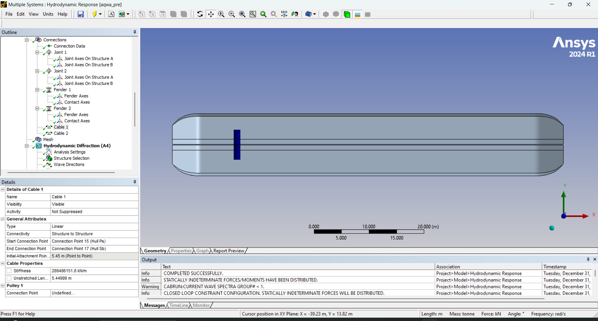
At the bottom, I modeled two fenders (forward and aft), as shown in the diagrams.
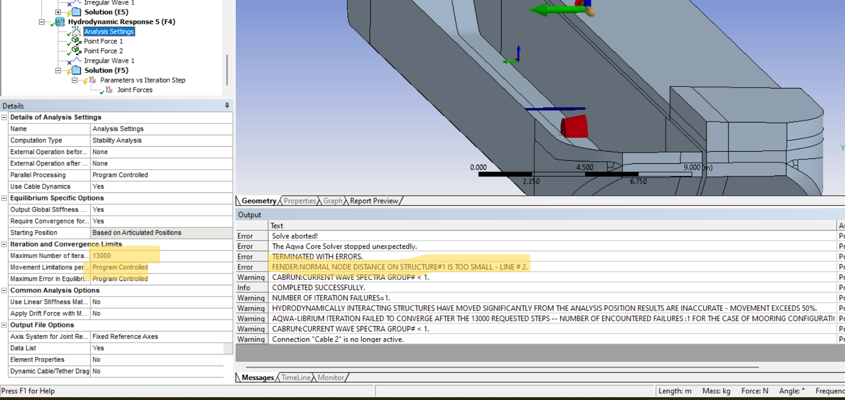
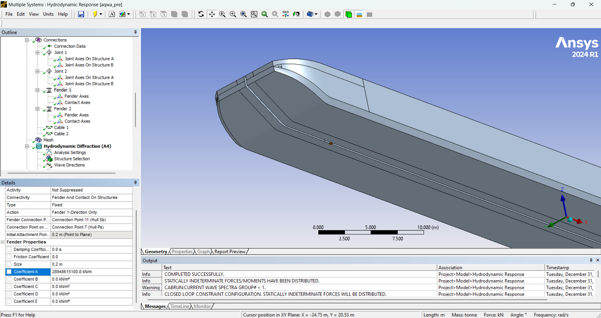
2. Simulation Results:
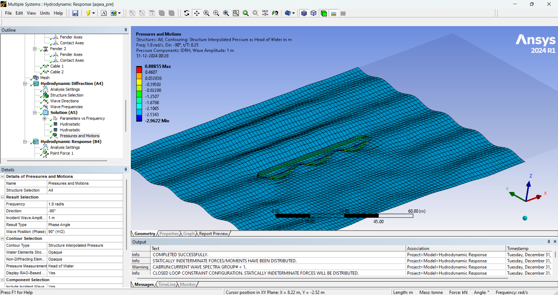
- Diffraction Analysis: The diffraction analysis ran successfully without any issues.
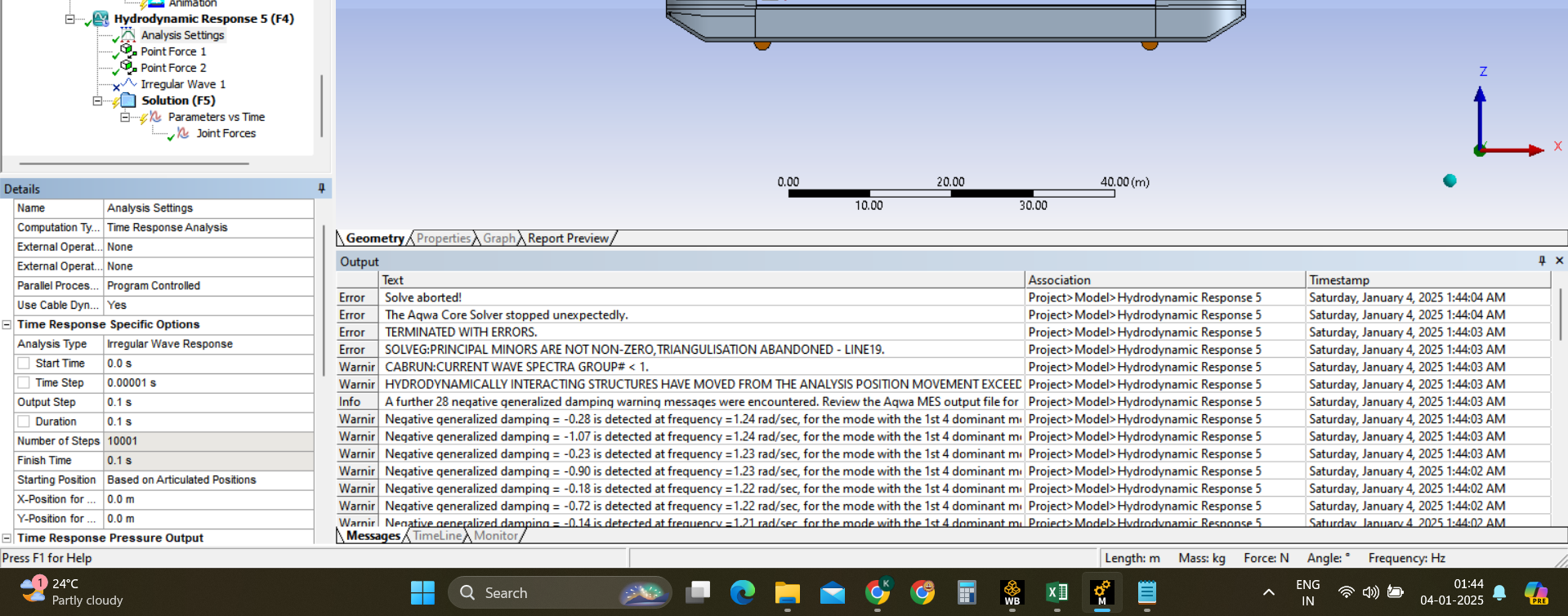
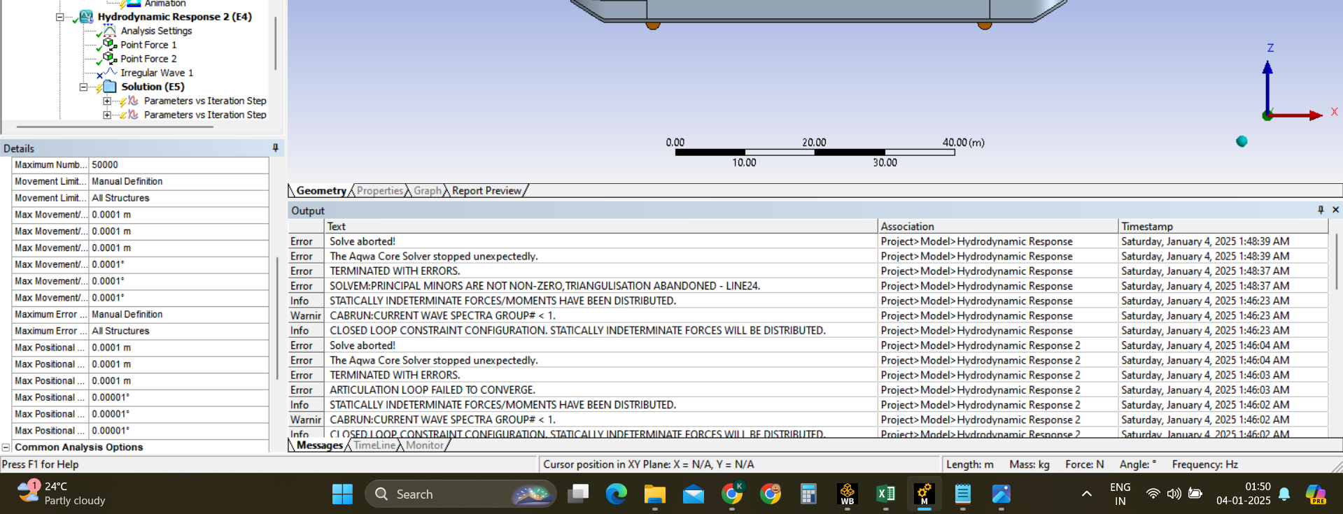
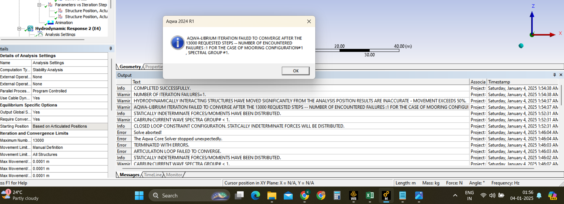
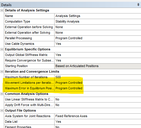
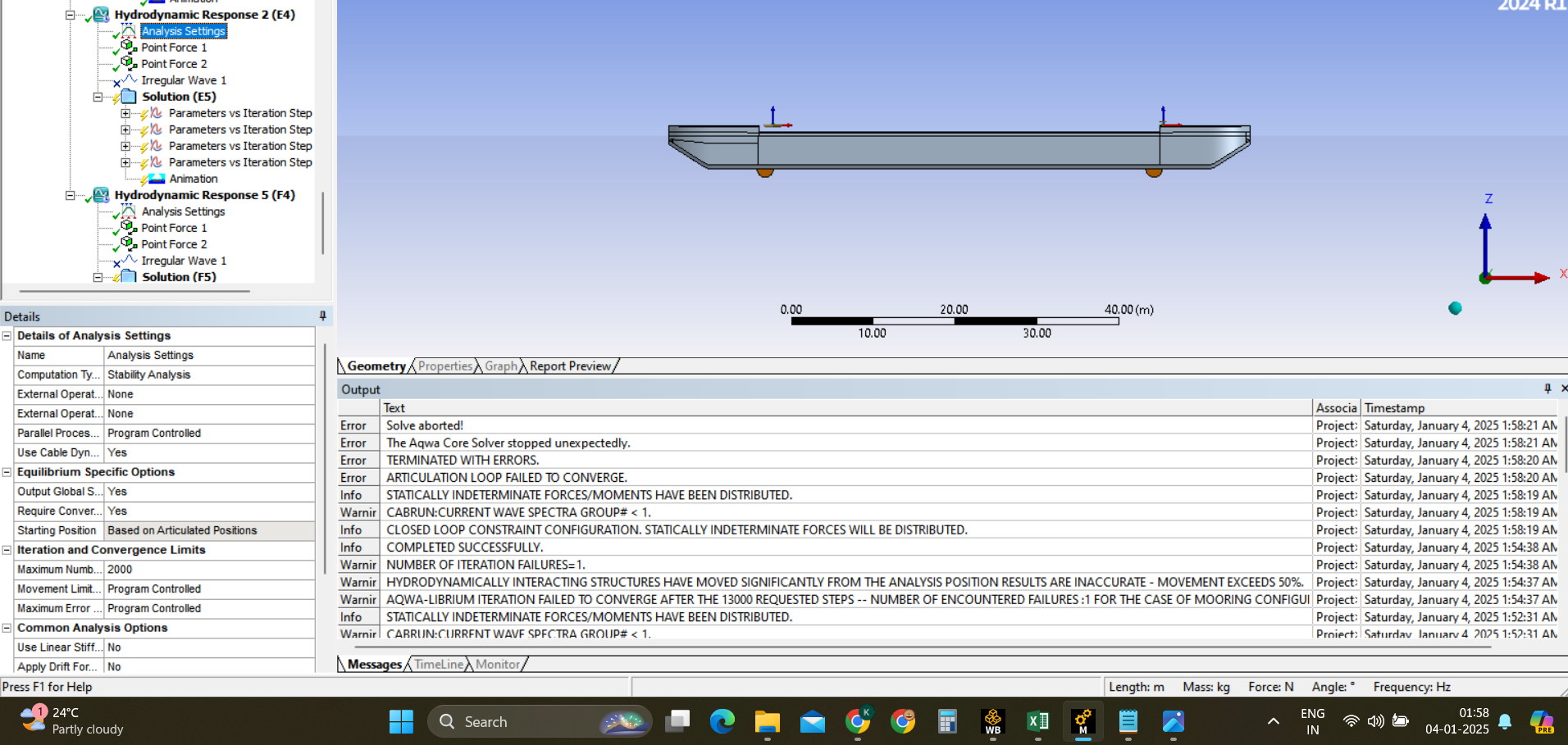
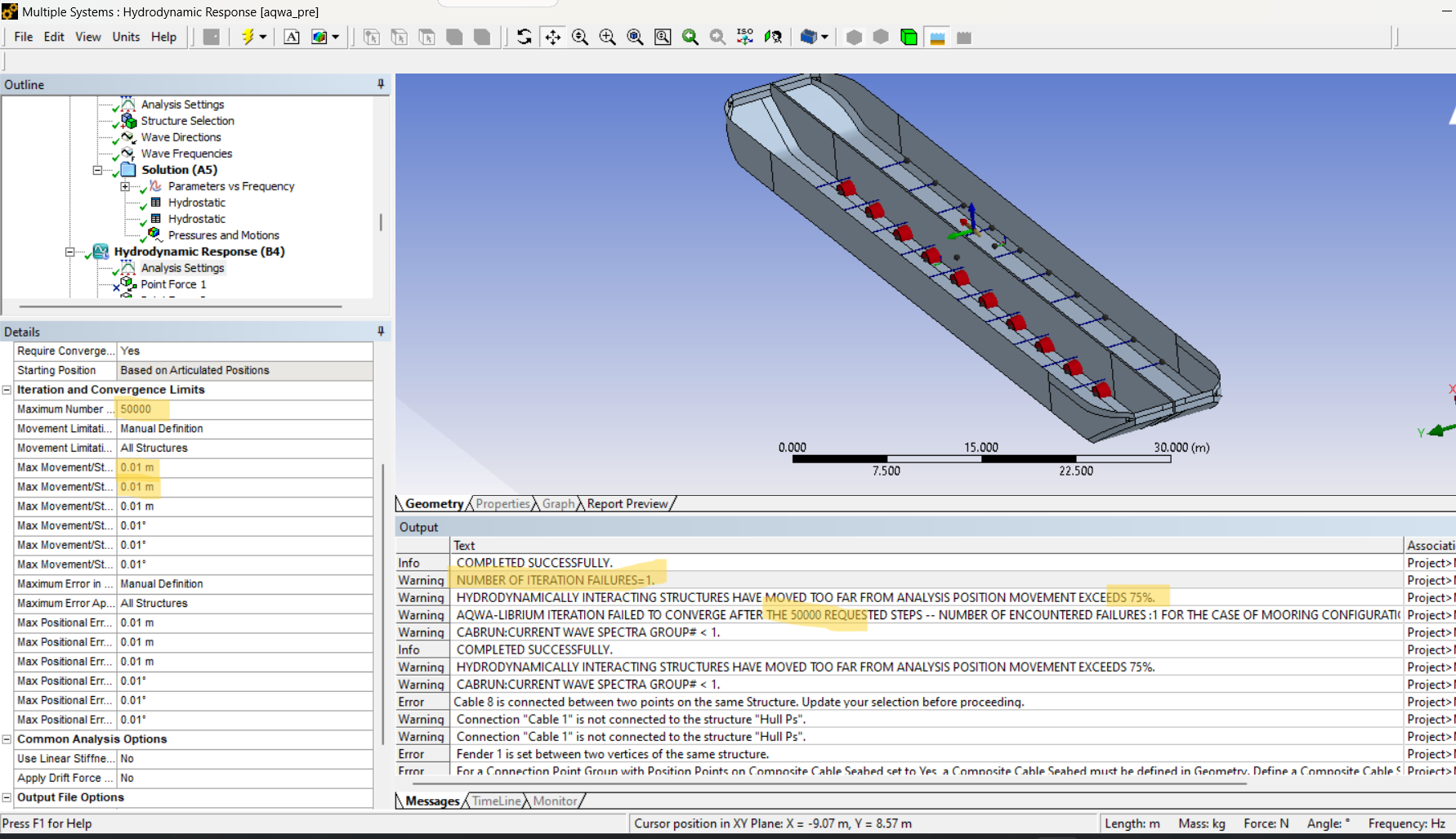
- During the stability analysis, the bodies are moving randomly, going above and below the water level unexpectedly.
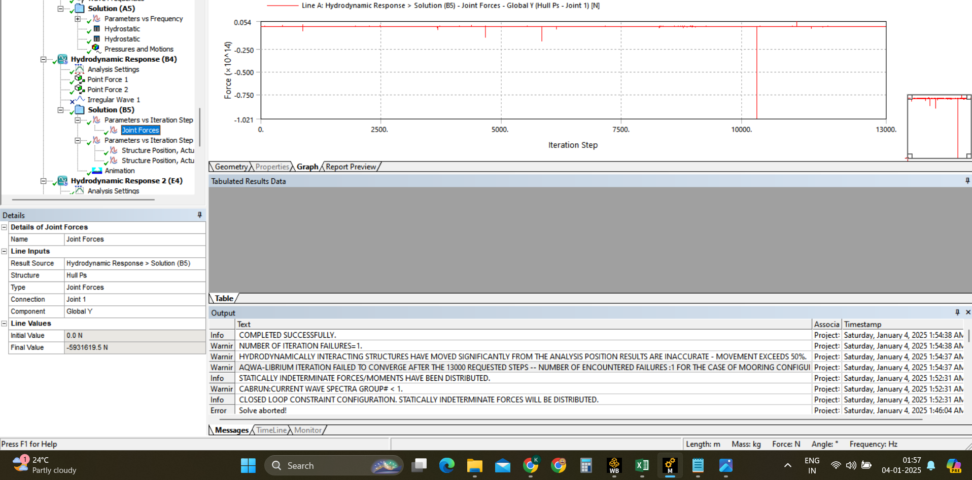
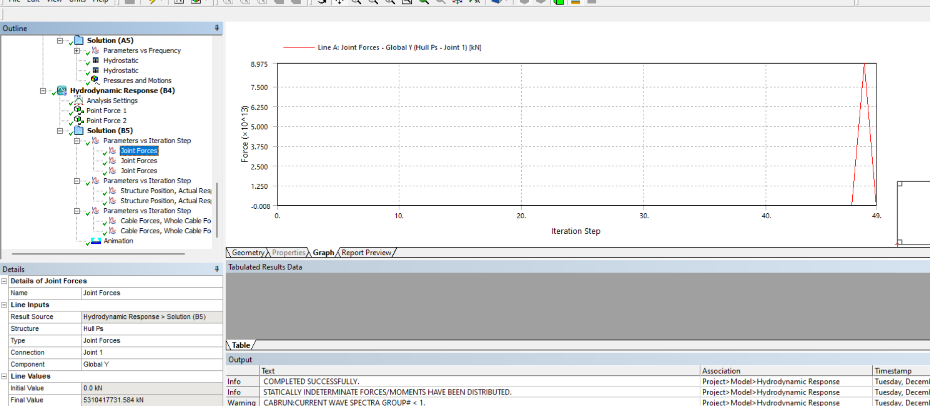
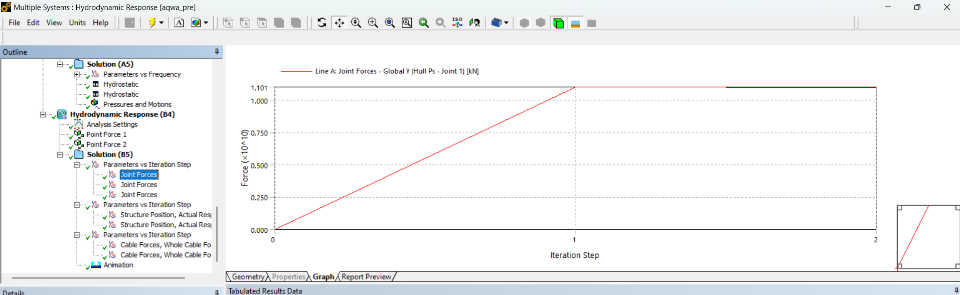
The lateral forces at the hinges are excessively high, reaching values as large as 10^11kN. These forces should ideally be around 900 kN, as per static calculations
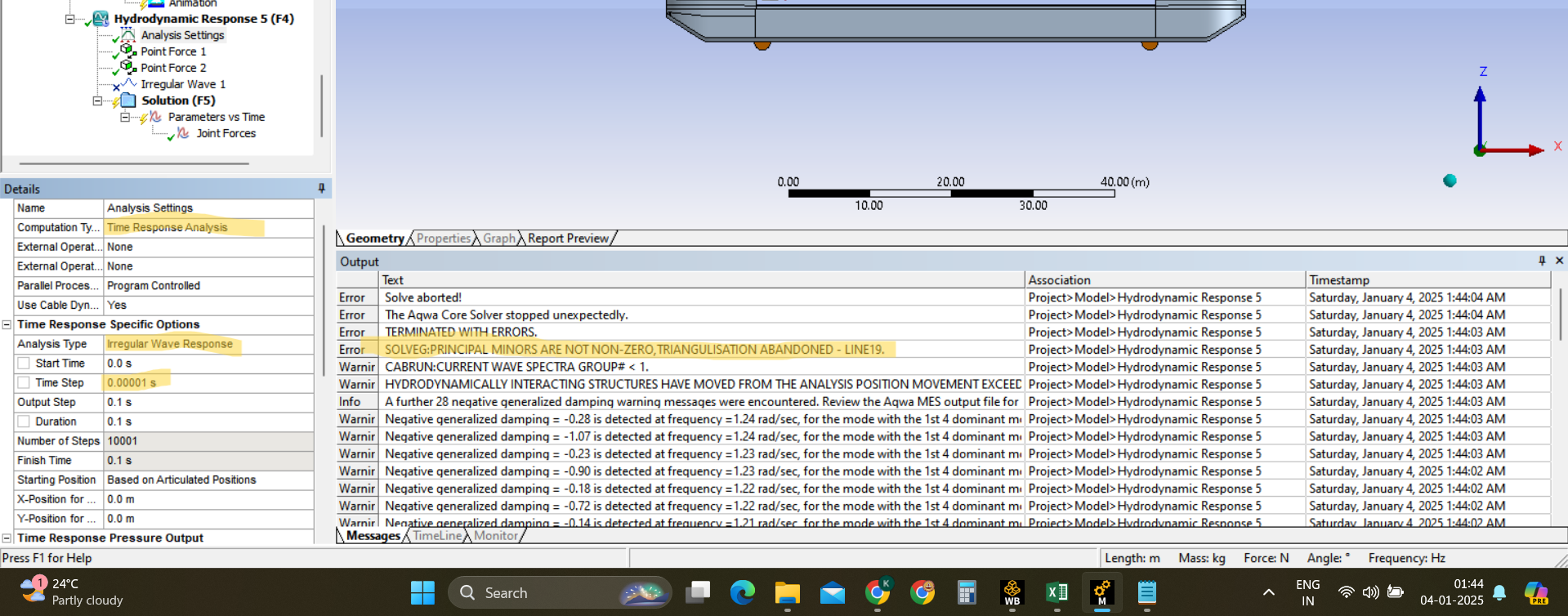
The time response analysis fails to run.
Â
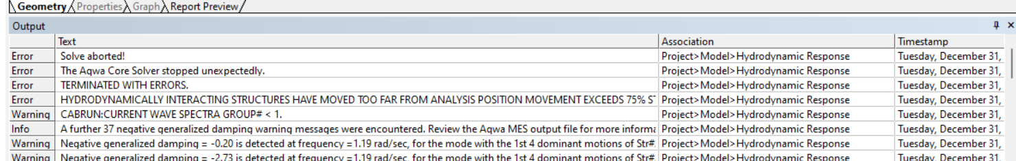
When attempting a simplified setup with a single hinge joint at the center of the vessel, the stability analysis does not converge.
Â
Using a fixed joint at the center also results in unrealistically high lateral forces, which are not physically accurate.
Â
Â
Request for Help:
I need this model for my thesis project and am looking for guidance on resolving these issues. Specifically:- Why are the bodies moving randomly in the stability analysis, and how can I resolve this?
- What could be causing the excessively high lateral forces in the hinges?
- Are there any specific changes to the joint setup or modeling approach that could improve convergence and stability?
I would greatly appreciate any insights or recommendations from the community. Thank you!
-
January 3, 2025 at 2:05 pmShuangxing DuAnsys Employee
The mooring stiffness and fender stiffness are 2.89e8 kN/m and 2.89e10 kN/m resepectively in your model, which may make the model's natural frequency to be very high and the forces on the joint/cable/fender are sensitive to the relative motions between the structures, which will require the very small maximum Error and Movement Limitations per Iteraton in the stabilty analysis and small time step interval in the time domain analysis.Â
To avoild this probl problem, I wonder if you can reduce these stiffness?
-
January 3, 2025 at 8:56 pmoe23m012Subscriber
Thanks for the reply
Â
The high stiffness in cable is required to simmulate the Hydraulic cylinder so that the hulls don't move away because of the large hydrostatic forces exerting on the hulls away from the centerline.Â
And the same thing withe fender stiffness tosimmulate the metal to metal contact between hulls so the arrangement between hinge, cable and fender will act like a class 3 leverÂ
Anyway i tried the analysis with the reduced stiffnessÂ
The inital length is reduced to simmulate the initial tension the cylinderÂ
Â
and the time doamain analysis gave error like this with a very small time step
And then stability analysis with following settings
But it stopped at 13696 iteration and throwed the above error so i gave 13000 iteration to get the idea of hinge load
Still the load is heigh
and with program controlled setting the following error came
So is there any chance to simmulate the Split hopper barge physics in ansys aqua.Â
-
January 6, 2025 at 10:07 am
-
January 9, 2025 at 3:48 amoe23m012Subscriber
 Hello sir,
Thank you for the responce
(1) in Stability analysis, using small Movement Limitations per iteration and small Maximum Error in Equilibirum Position.Â
And i am getting the above error at 13696 iteration
(2) Using small time step in time domain analysis.
The error is consistent with several iterations
Â
-
January 9, 2025 at 9:51 amShuangxing DuAnsys Employee
I guess that you used two joints on the deck in this calculation. If it is true, could you please just use one hinge joint only? For rigid body response analysis of this model, the socond universal joint has no effect on the motion responses, but may cause the singularity problem of the response equations.
-
January 10, 2025 at 3:06 pmoe23m012Subscriber
-
January 10, 2025 at 3:27 pmShuangxing DuAnsys Employee
From the picture below, it seems that there are lots of fenders and cables.
Do the highlighted surfaces physically exist? If yes, in the Hydrodynamic Diffraction analysis, please set these surfaces as non-diffractional, as they are too close to each other. By doing so, the fluid dynamic effects between the gap of these surfaces are ignored, which could make your analysis to be more stable. If not, there is no need to define these surfaces.
-
- You must be logged in to reply to this topic.
- How do I get my hands on Ansys Rocky DEM
- Non-Intersected faces found for matching interface periodic-walls
- Unburnt Hydrocarbons contour in ANSYS FORTE for sector mesh
- Fluent fails with Intel MPI protocol on 2 nodes
- Help: About the expression of turbulent viscosity in Realizable k-e model
- Cyclone (Stairmand) simulation using RSM
- Mass Conservation Issue in Methane Pyrolysis Shock Tube Simulation
- Script Error
- Facing trouble regarding setting up boundary conditions for SOEC Modeling
- convergence issue for transonic flow
-
1557
-
602
-
599
-
591
-
366
© 2025 Copyright ANSYS, Inc. All rights reserved.