-
-
November 15, 2022 at 4:48 am
charles delepelaire
Subscriberhi all, ti try to use fluent, so i've tried to simulate flow fluid around a 2mm ball inside a 1 liter fluid box (100x100x100 mm)
ball is the ridiculous sized point at the center of the french flag
Â
so... from here we can saw :Â
Cd of a smooth sphere around 0.47 at 5m/s and around 0.08 at 30m/s (see graph)
i've made a coefficient drag report file with it's plot with Y force Vector set to 1.
and the computation zone setted to my ball mesh
Â
anyway i'm not able to find these values, and furthermore i got plethore amout of value dependant of intialisation caractéristic like hybrid/standard or pressure/density based... etc...
Â
so what can i do to get repeatability, accuracy and "good" value with my simulation ?
-
November 15, 2022 at 6:35 am
Nikhil Narale
SubscriberFirst thing, any reason for this? "plot with Y force Vector set to 1."Â
Is the fluid flowing along the Y axis?Â
-
November 15, 2022 at 7:06 am
charles delepelaire
Subscriberyes fluid flow along Y axis
-
-
November 15, 2022 at 6:42 am
Nikhil Narale
SubscriberHow good is your mesh near the object (ball)? Can you post the screen grab of the cut section of the volume mesh? Â
-
November 15, 2022 at 7:20 am
-
-
November 15, 2022 at 7:45 am
Nikhil Narale
SubscriberÂ
This doesn’t look like a cut section. Did you add inflation layers?Â
Â
Edit: Just saw the second image.Â
-
November 15, 2022 at 7:46 am
charles delepelaire
SubscriberÂ
no inflation no (adding too much node inside student license)
Â
-
-
November 15, 2022 at 9:05 am
Nikhil Narale
SubscriberFor getting accurate results, it is very critical to have a mesh with good resolution and quality, at least near to the object of your interest. I would suggest you to look for aero meshing tutorials (airfoil for that matter) on the internet.Â
Also, keep a keen eye on the y+ value and make sure to maintain it as per the best practice. To know more, check this: 4.18.1. Overview (ansys.com)
If you are not able to access the link, please refer to this forum discussion: Using Help with links (ansys.com)
Â
Nikhil
-
November 15, 2022 at 10:41 am
charles delepelaire
Subscriberok so do you suggest to make it in 2D and analysis one vector at a time ?
is needed to get a symetric mesh ?
-
November 15, 2022 at 11:43 am
Rob
Forum Moderator2d has it's own problems as the wake separation may be asymmetrical and 2d-axisymmetric will mask that. Inflation shouldn't add too much to the cell count, and some careful decomposition should mean you can tet only the near sphere region and hex the rest.Â
Also, check sphere projected area and then read up on wind tunnel blockage factors. The domain looks fairly big relative to the sphere so you may be able to save some cells that way.Â
Finally, Student is intended to help you learn how to use the software. That includes realising you need a bigger mesh to get the right answer, and is why we also have Research licences.Â
-
November 18, 2022 at 9:20 am
-
November 18, 2022 at 10:36 am
Rob
Forum ModeratorUse inflation and resolve the wake region. The graphs will show you the quality of the cells, what you're lacking is resolution of the boundary layer, separation and wake regions. Read the Body of Influence part here https://ansyshelp.ansys.com/account/Secured?returnurl=/Views/Secured/corp/v222/en/flu_ug/tgd_user_sf_types.html%23tgd_user_sf_boi to show how I'd mesh this. In Ansys Meshing the functions are there, but the images are better in the Fluent Meshing documentation.Â
The data you get from your model will not be accurate, but the general principle is shown.Â
-
November 18, 2022 at 11:11 am
-
November 18, 2022 at 12:02 pm
Rob
Forum ModeratorBetter. You may find you need more mesh via a BOI in the wake and more inflation layers but give it a go.Â
-
November 18, 2022 at 12:14 pm
-
November 18, 2022 at 1:36 pm
Rob
Forum ModeratorYes, like the image. You may not need to go as far downstream though.Â
No idea about the second bit of a quote. Two posts are fine.Â
-
November 18, 2022 at 2:43 pm
charles delepelaire
Subscriberok but the probleme is how can i make a sphere of influence shaped like an ellipsoïd ?
-
-
November 18, 2022 at 2:48 pm
Rob
Forum ModeratorCreate a block & chamfer or curve & rotate: you do this in SpaceClaim or DesignModeler. As it's just a shape to guide the mesh refinement it's not required to be a perfect shape - a cuboid wedge will be fine.Â
-
November 19, 2022 at 4:20 pm
-
November 20, 2022 at 9:35 am
charles delepelaire
Subscriberup
-
November 21, 2022 at 1:18 pm
charles delepelaire
SubscriberÂ
re-up
[EDIT] is there a reason when i up my message it's not upped ?
Â
-
November 22, 2022 at 11:53 am
Rob
Forum ModeratorThe system sort is new threads, or recent activity, you may have the wrong sorting option selected. As I also receive emails to tell me something has been added there's no need until you've not heard for a few days. Bumping after a day isn't appreciated, and will result in a miffed support engineer.Â
Given how coarse your new mesh is, how big a jump in cell size over the interface and how close it is to the region of interest, then no, it's not better. Have a look at the airfoil/aerofoil tutorials (might be NACA) and see how they've been meshed. Then read up on body of influence as you've split the zone out.Â
-
November 22, 2022 at 4:48 pm
-
November 22, 2022 at 4:51 pm
Rob
Forum ModeratorMuch better. The order shouldn't matter as the tool ought to take the smallest cell from each: it's why it takes some time before building the mesh.Â
-
November 22, 2022 at 4:54 pm
charles delepelaire
Subscriberi have this warning :
"Hard edges are not supported and may be ignored for pre-inflation, please check your model carefully."
is it important ? -
November 22, 2022 at 4:57 pm
Rob
Forum ModeratorDepends on where the hard edges are! A hard edge is an edge that doesn't form part of a surface perimeter: https://ansyshelp.ansys.com/account/Secured?returnurl=/Views/Secured/corp/v222/en/wb_dm/dm3dRepairHardEdges.html has an image showing what they are.Â
-
November 22, 2022 at 5:08 pm
charles delepelaire
Subscriberwhen i go to warning-> show problematic geometrie it's seems it's edge of my ball and edge outside my enclosure.
Â
so will i try to make my fluid flow simulation anyway ?
-
-
November 22, 2022 at 5:31 pm
Rob
Forum ModeratorIf the mesh checks OK, yes. Warnings are something to check out and understand, they may not be important on any one occasion but MUST be checked.Â
-
November 22, 2022 at 5:57 pm
charles delepelaire
SubscriberÂ
this is the mesh quality :
Mesh Quality: Minimum Orthogonal Quality = 2.81099e-01 cell 61822 on zone 2 (ID: 61823 on partition: 0) at location (-2.28725e-02, -9.77421e-02, 6.04073e-03) Maximum Aspect Ratio = 8.38496e+00 cell 85645 on zone 2 (ID: 85646 on partition: 0) at location ( 1.20744e-03, -8.94578e-04, 3.44995e-04)
Â
i maked it polyhedra, that’s good ?
Â
-
November 23, 2022 at 9:47 am
Rob
Forum ModeratorCell quality is good, you'll know if the resolution is suitable once it's run.Â
-
November 23, 2022 at 1:59 pm
charles delepelaire
Subscriberso the probleme persist, why can't i get planned result ?
-
November 23, 2022 at 3:36 pm
Rob
Forum ModeratorWhat are you seeing? Have you checked the reference values for the coefficients?Â
-
November 23, 2022 at 3:55 pm
charles delepelaire
SubscriberÂ
oops i forgot to edit my precedent post :
Â
surface area : 3.14E-6 m² (section surface of my ball)
pressure : 101325 Pa
length :0.002 (diameter of my ball)
velocity : 5m/s
fluid velocity at inlet : 5m/sÂ
density based and steady solver
all reamaining seems to be default
computation from my ball, 200 iterations (need i to add more until i get convergence ?)Â
i tried laminar and k-omega analysis with different option...
Â
Â
-
-
November 23, 2022 at 4:28 pm
Rob
Forum ModeratorIf the flow is over about Mach 3 then density based may be needed, but mostly pressure based is fine.Â
Convergence is recommended, otherwise the results tend to be a little wrong. That's why we have convergence residuals, and plot monitors.Â
-
November 27, 2022 at 1:48 am
charles delepelaire
SubscriberÂ
Â
Â
Â
hahaha
hi everyone, after few day to take fluent in hand i think i have finally understood why my first results went wrong.
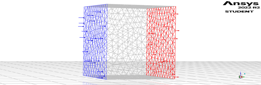
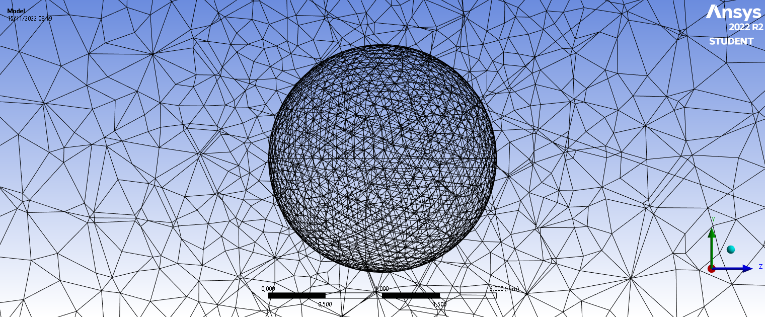
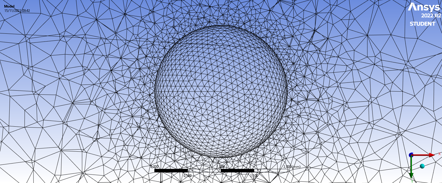
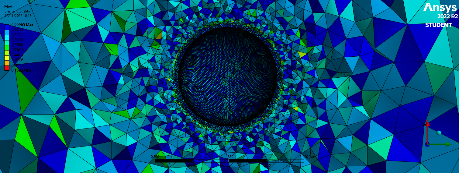
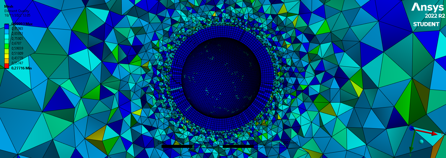
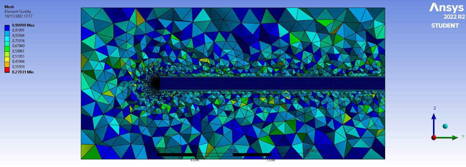
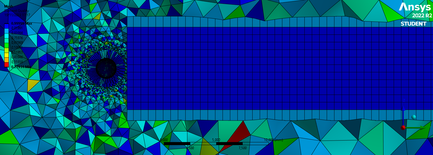
i made enclosure, ball and BOI volume from Fusion 360, and export them to step files, so maybe there is a problem beetween fusion and fluent.
here are the fusions files : grosfaignan/3d-files (github.com)
if anyone can test them and help me.
Â
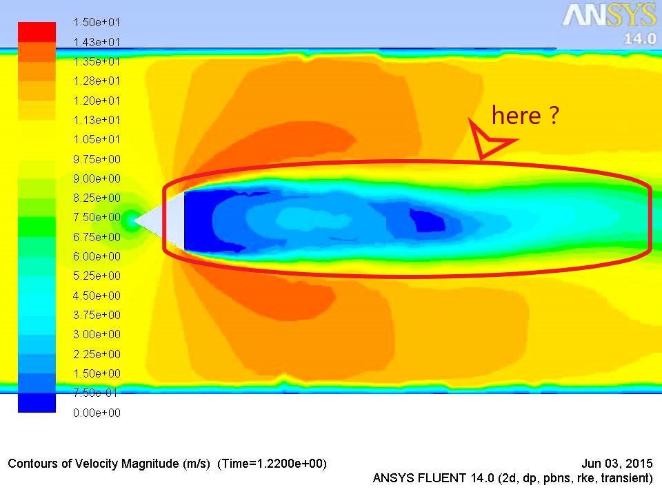
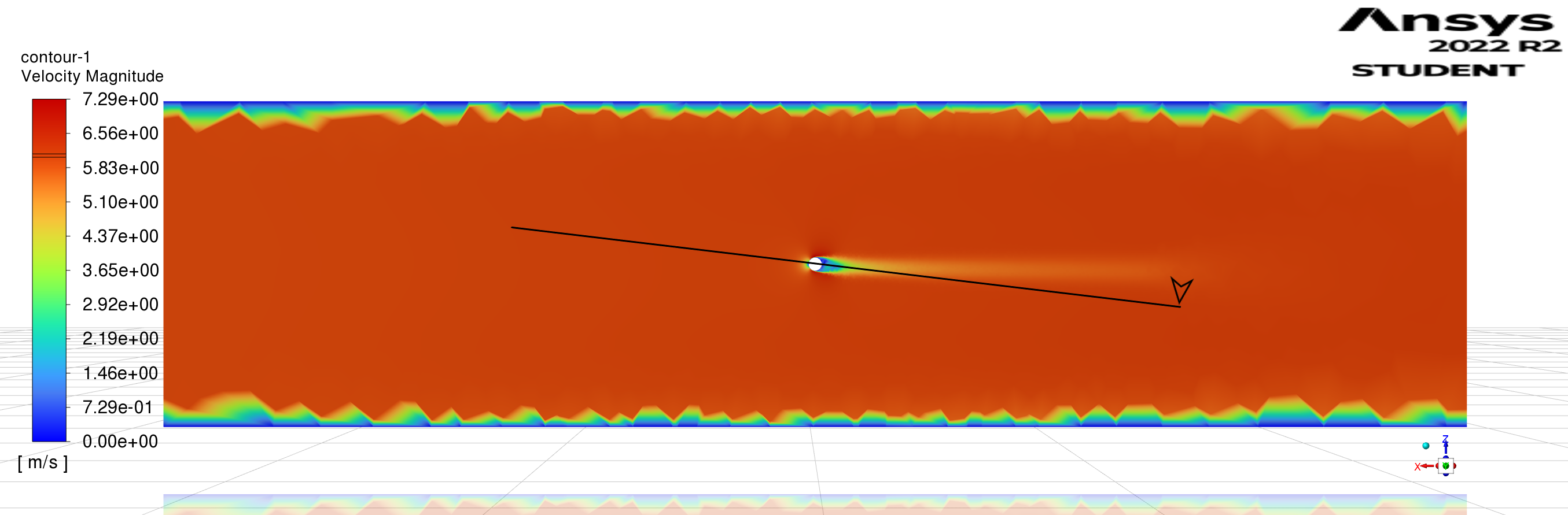
but now i have another problem, i have a good drag coefficient, but in a wrong direction :
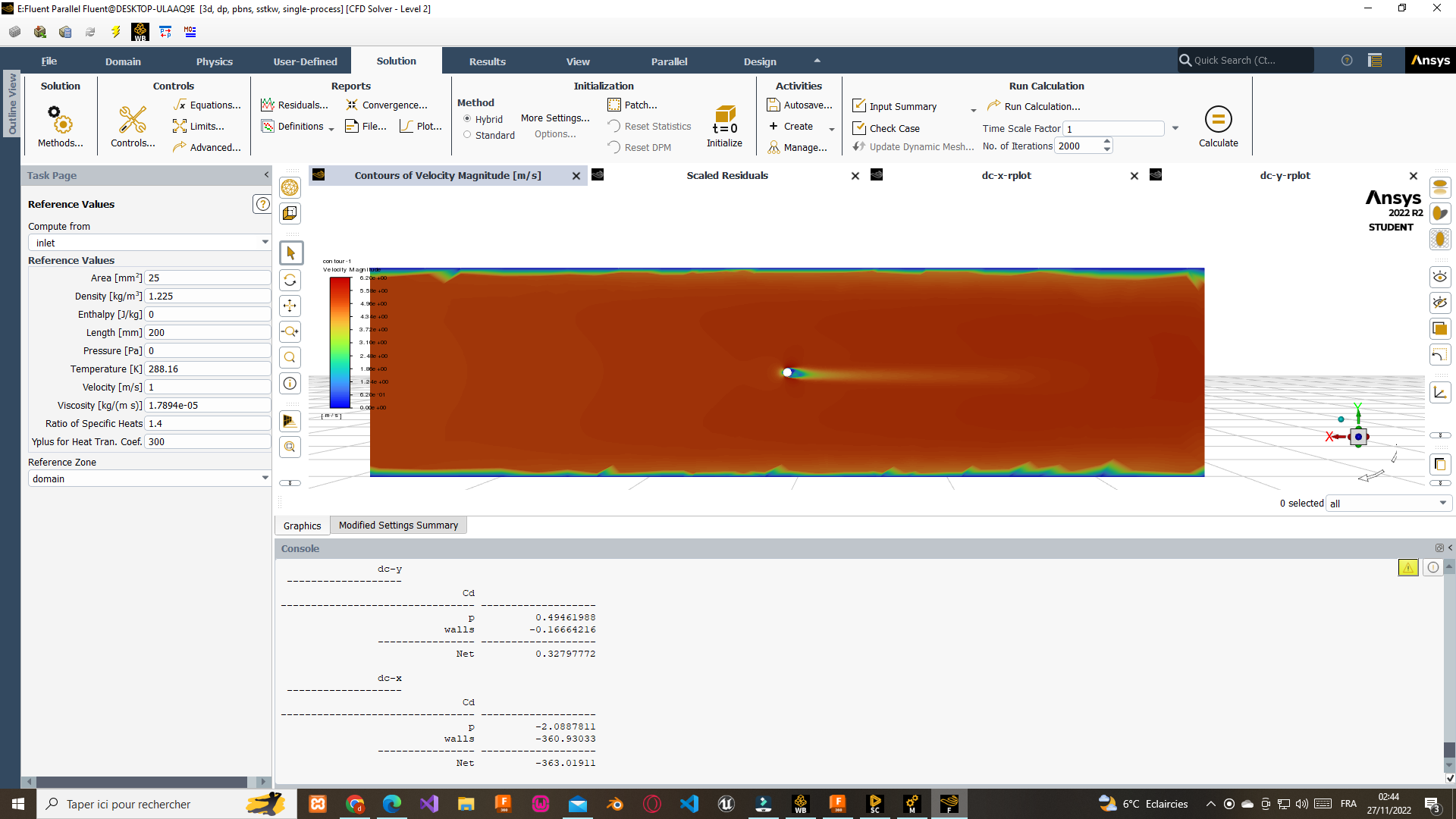
since i used spaceclaim 3d model, inlet and outlet are aligned to X and not to Y, so why getting good results along the wrong axis ? (in screenshot above, P drag coefficient in Y is around 0.49 for a 5m/s velocity at inlet, good result, wrong axis)
[EDIT]hahaha no, after a second test at 30m/s when i need to get a 0.1drag coef it seems it’s a false positive
[EDIT2] another misunderstood :
if i have flow velocity setted from inlet to outlet, so in this case parrallel to X axis, why Y and Z coefficient drag calculation are different ? see beelow :
===================
dc-x
Cd p = -16.622681
===================
dc-y
Cd p = 3.9403545
===================
dc-z
Cd p = -1.9091926 -
November 29, 2022 at 9:55 am
Rob
Forum ModeratorLooking at the flow field the wake isn't aligned with the axis, that'll influence the coefficients, and mess with the convergence.Â
Step tends to transfer well, so unless the scaling went awry that shouldn't cause a problem.Â
-
November 29, 2022 at 1:36 pm
-
-
November 29, 2022 at 4:21 pm
Rob
Forum ModeratorBy looking: remember I've been doing this longer than you! Wakes, especially on spheres and cylinders tend not to be symmetric as you can get eddy shedding: look up von Karman vorticies.Â
Â
-
- The topic ‘Drag coefficient’ is closed to new replies.
-
2788
-
965
-
851
-
599
-
591
© 2025 Copyright ANSYS, Inc. All rights reserved.