-
-
March 17, 2022 at 11:01 am
Richard111
SubscriberHi all,
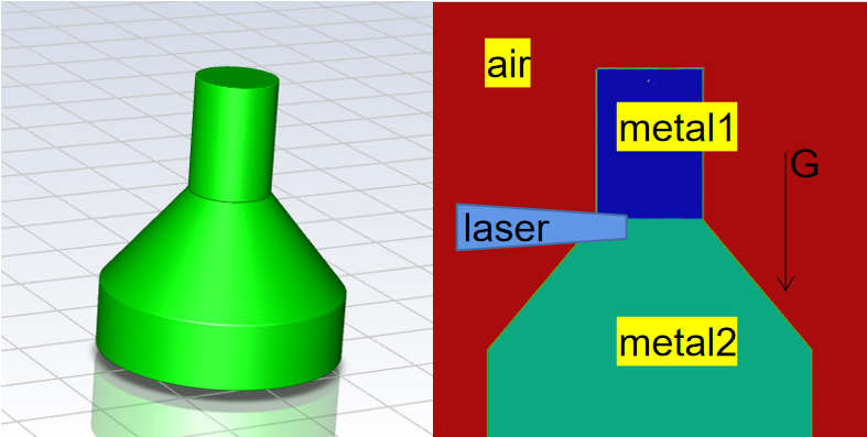
I I've been trying this laser welding simulations for a long time, The results were very disappointing,I have set 2 phase with VOF model, air phase and mix metal phase with species model. The dome of model as showing in fig 1., The mesh Minimum Orthogonal Quality is 0.4.
March 17, 2022 at 11:38 amRob
Forum ModeratorAre you using the solidification and melting model?
March 17, 2022 at 1:18 pmRichard111
Subscriberyes solidification and melting´╝î VOF and species model
March 17, 2022 at 1:22 pmRob
Forum ModeratorWhat are the liquid and "solid" thermal properties? As it's a fluid model we'd expect some distortion around the free surface but what you're seeing is excessive.
March 17, 2022 at 3:51 pmRichard111
SubscriberI tried both udf define and polynomial, Due to other parameters such as density, thermal conductivity and cp has little effect,
like: conductivity of Ni
if (temp >= 300 && temp < 1717)
de2_value = 0.0212*temp + 39.439;
else if (temp >= 1718 && temp < 3100)
de2_value = 0.0209*temp + 16.705;
else
de2_value = 20;
return de2_value
and different value of viscosities and surface tensions in "solid" state are tried, such as very high(100000) or low(0.000001) viscosity, like:
real viscosity;
if (1717 <= temp <= 3100)//liquid
viscosity = 0.88988*exp(-temp / 288.7727) + 0.01404*exp(-temp / 1014.5192) + 4.67366E-4;
else if (3100 < temp)//gas
viscosity = 0.00061;
else
viscosity = 100000.;//solid
return viscosity
DEFINE_PROPERTY(surf_tension, c, t)
{
real surf;
real temp1 = C_T(c, t);
if (temp1 >= 1714)
surf = 1.0 - 0.0003*(temp1 - 1714);
else if (temp1 >= 3100)
surf = 0.41;
else
surf = 0.0000001;//
return surf;
}
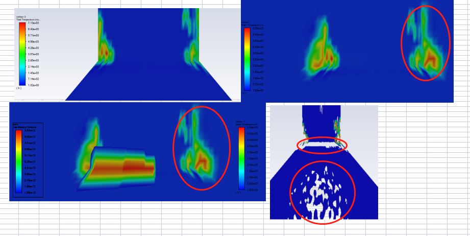
and U got the point, the distortion around the free surface in my model is abnormal, the mass transport between air and metal is not right, and it can spontaneous appearance.
and warning like temperature limited to 1.000000e+00 in 12702 cells on zone 8 in domain 1, It doesn't make sense, I don't in what process cell needs to absorb energy and temperature reduce to 1K.
March 17, 2022 at 4:10 pmRob
Forum ModeratorThe limiter warnings tend to mean the solution is in the process of diverging, that can then trigger all sorts of daft results.
Check the IF statements, what happens if T=1717.5K ? Drop the time step by a couple of orders of magnitude and see how it performs.
March 17, 2022 at 8:11 pmMarch 18, 2022 at 9:38 amRob
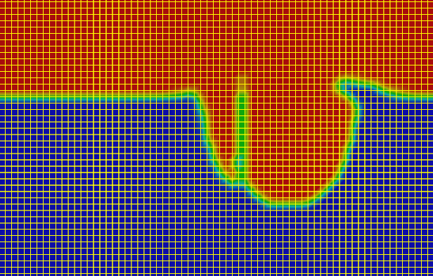
Forum ModeratorCan you post an image of the mesh? In the first images it looks OK, but in the last couple the cell aspect ratio looks high.
Once the solution fails you may find odd artefacts in the contours as the plot range gets silly.
March 18, 2022 at 2:40 pmRichard111
SubscriberSorry to bother you at weekend, I tried different mesh, Structural Mesh or Unstructral Mesh, some mesh with high aspect ratio, but I tried a box mesh , and diverged and few time step(1*10^8)ÒÇé
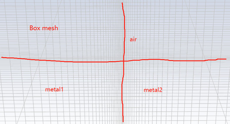
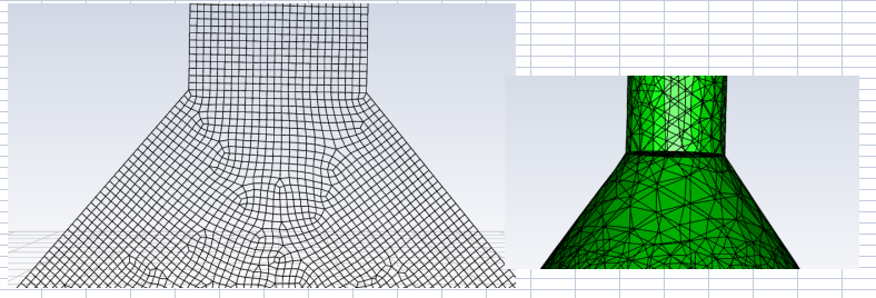
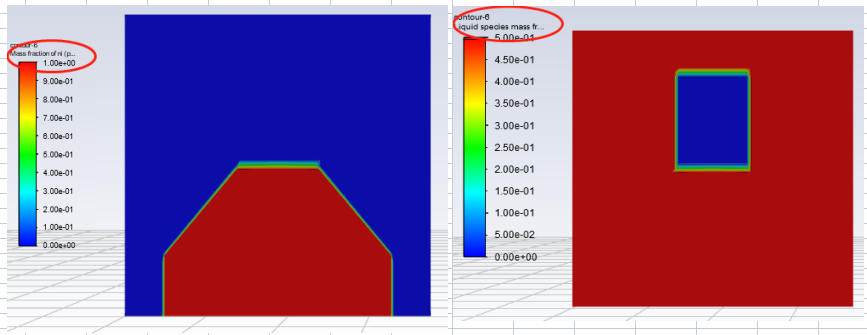
 And, I just find out mass fraction and Liquid species mass fraction are different after patch, the liquid species fraction of metal shouldn't it be equal to 0?
March 18, 2022 at 2:48 pmRob
Forum ModeratorIt's not the weekend yet, some of us work on Friday afternoons! ;) I stopped being a student a little over 20 years ago....
The mass fraction of the phases should make sense, but check what you initialised with and then patched. I'd initialise the domain using "standard" and all being air. I'd then patch the two "solid" regions along with the temperature. The scale on the right is 0 to 0.5 which suggests something got mixed up: you may need to patch to "zero" and then "one" for materials.
For the mesh you want a smooth growth rate and low aspect ratio in the melt regions. You also want at least 5-10 cells across the melt region to capture the gradients.
March 18, 2022 at 3:51 pmRichard111
Subscriber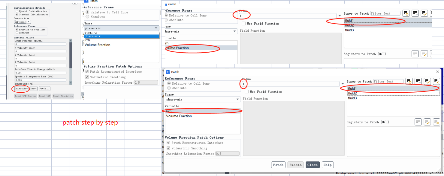
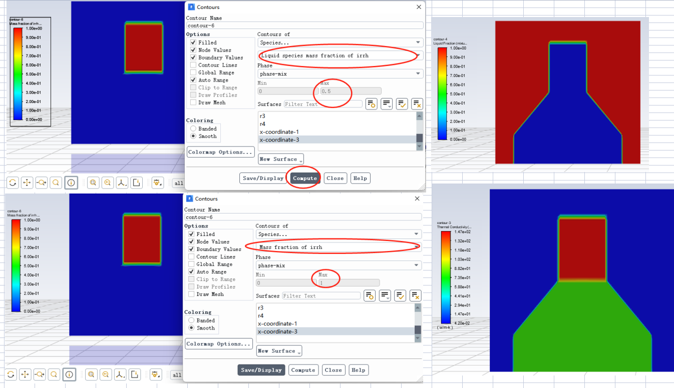 I think my patch step is right, I'm not sure that the Liquid species mass fraction at 300K is 0.5 is right or bug.
I'm sure the cells across the melt region more 10 cellsÒÇé
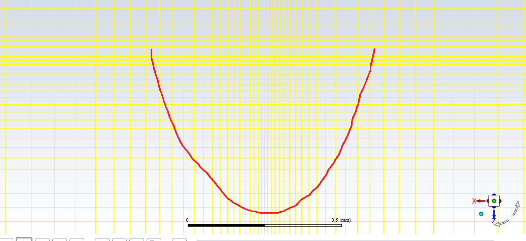 Bty, Is this really possible to simulate case like this? Including VOF, species and solidification and melting.
Because I can find only one paper´╝î which is ÔÇ£Numerical simulation of alloy composition in dissimilar laser welding ÔÇØ byM.R. Nekouie Esfahani, they did a similar case, and I'm not sure they used species model, and the heat source is surface heat source. Some dissertation present similar case as well, by the joint mode is different´╝îwhich is lapjoint, it means that the heat source does not apply directly on both metal.March 18, 2022 at 4:38 pmRob
Forum ModeratorMelt region is vertical too - what do you expect to become liquid?
The species looks odd, check what you're looking at as whilst we can model species in VOF and then melt them I'm not sure what the reporting looks like without building a model.
March 19, 2022 at 7:23 amRichard111
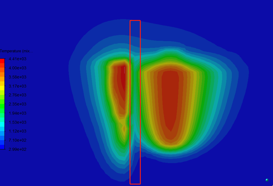
SubscriberI'm tying to get some result like this, mass transport in the welding seam.
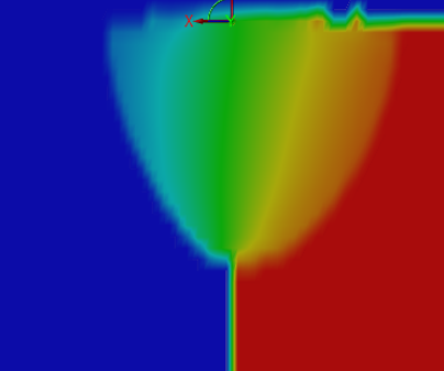
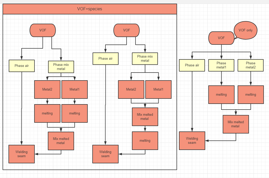
The computational logic should be like figure below left one, metal melting first then mix, But I think Fluent computational logic is mid one , which is mix species base on volume volume fraction or mass fraction, so is irrelevant to temperature, If I use Vof model only, then no mass transport.
March 21, 2022 at 9:50 amViewing 13 reply threads- The topic ‘Dissimilar Materials laser welding simulation(2020R2)’ is closed to new replies.
Innovation SpaceTrending discussionsTop Contributors-
4613
-
1520
-
1386
-
1209
-
1021
Top Rated Tags© 2025 Copyright ANSYS, Inc. All rights reserved.
Ansys does not support the usage of unauthorized Ansys software. Please visit www.ansys.com to obtain an official distribution.
-
The Ansys Learning Forum is a public forum. You are prohibited from providing (i) information that is confidential to You, your employer, or any third party, (ii) Personal Data or individually identifiable health information, (iii) any information that is U.S. Government Classified, Controlled Unclassified Information, International Traffic in Arms Regulators (ITAR) or Export Administration Regulators (EAR) controlled or otherwise have been determined by the United States Government or by a foreign government to require protection against unauthorized disclosure for reasons of national security, or (iv) topics or information restricted by the People's Republic of China data protection and privacy laws.

