TAGGED: #fluent-#ansys
-
-
December 19, 2023 at 12:08 pm
Elisa Revello
SubscriberHi everyone,
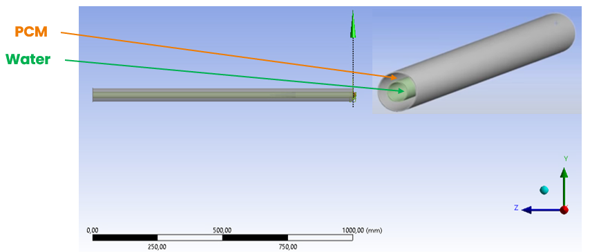
I am working on the simulation of the melting process of a PCM. I created on ANSYS DM a geometry with two concentric cylinders, where in the inner pipe flows an heat transfer fluid (water), while in the outer one is enclosed a PCM, as reported in the picture below:
I created a new material with the following properties:
Initially the temperature field of paraffin is set to 300 K (melting temperature is around 322 K and 328 K), the inlet BC are mass flow rate of water 0.05 kg/s and temperature of the inner pipe of 400 K. The outer pipe was set to adiabatic condition.
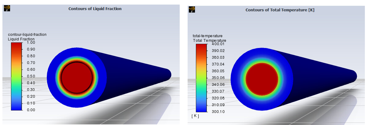
I have obtained the following contour plots for liquid fraction and temperature:
Now I want to graphically visualize:
- The phase change on a time-temperature diagram with Fluent
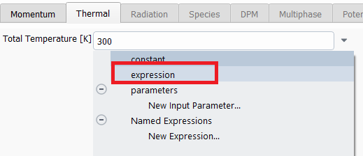
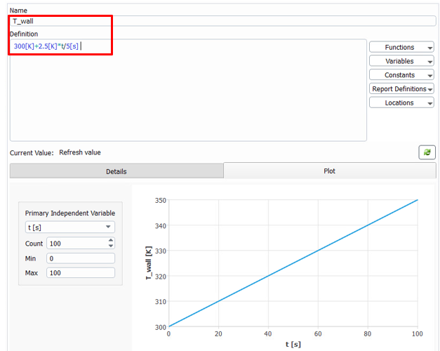
- Change the boundary condition of the inner pipe from constant temperature to temperature profile (function of time) with a Named Expression
How can I do this?
Best regards
-
December 28, 2023 at 1:40 pm
Vishesh Aggarwal
Ansys Employee- To visualize the phase change, please create a report definition using Volume Monitors > Mass Integral of Liquid fraction in the PCM domain. This will provide you a change in the liquid mass (starting from zero in your case) over time.
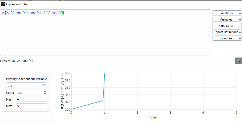
- The boundary condition can be set using an expression like below (this would depend on the expression you have!)
Hope this helps.
Cheers,
Vishesh
-
December 30, 2023 at 11:29 am
Elisa Revello
SubscriberMany thanks for the answers.
I have tryed to implement a time-dependent temperature profile (like below) for the BC of the inner pipe_outerwall.
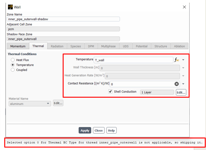
Since in the previous simulations (with thermal coupled BC for inner pipe_outerwall) I have activated the shell conduction between the two pipes (water and PCM outside are not directly in contact, the two pipes are 0.001m thick), now with a T_wall expression Fluent returns the following error message. Thus, should I deactivate the shell conduction?
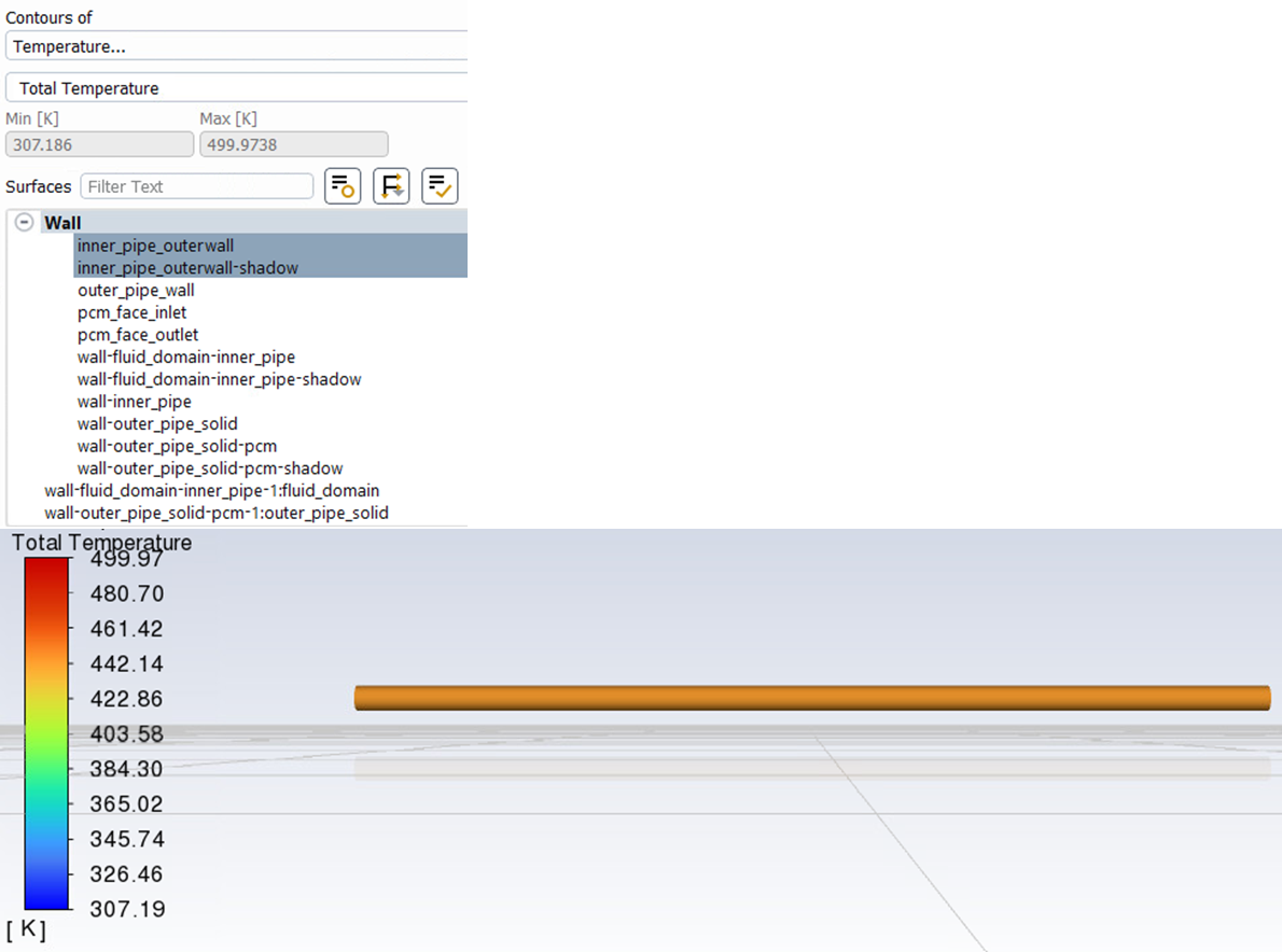
The contour plot of temperature in the inner tube obtained (deactivating the shell conduction) is the following, but it seems that the boundary condition defined (T_wall) is not respected.
How can I solve this problem?
Many thanks,
Best regards
-
January 2, 2024 at 7:24 am
Vishesh Aggarwal
Ansys EmployeeHi Elisa,
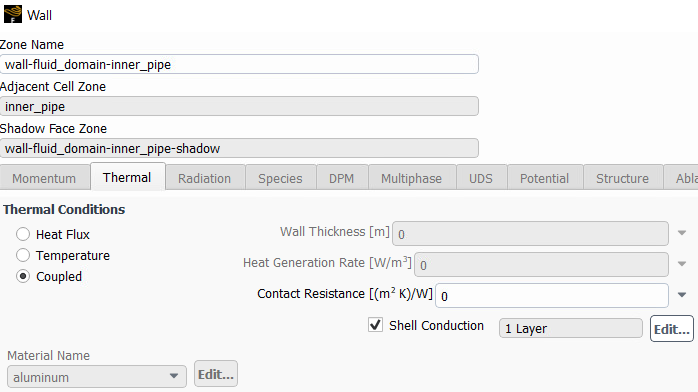
When you use the "temperature" option on the coupled wall, the wall and its shadow become thermally de-coupled since you want to impose a temperature BC. However, this uncoupling will not be effective if you have enabled shell conduction for the wall. The two uncoupled walls can have different wall temperature curves and thicknesses, and are effectively insulated from one another.
Hope this helps.
Regards,
Vishesh -
January 25, 2024 at 12:33 pm
Elisa Revello
SubscriberHi Vishesh,
Thanks for your feedback.
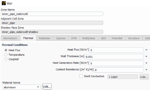
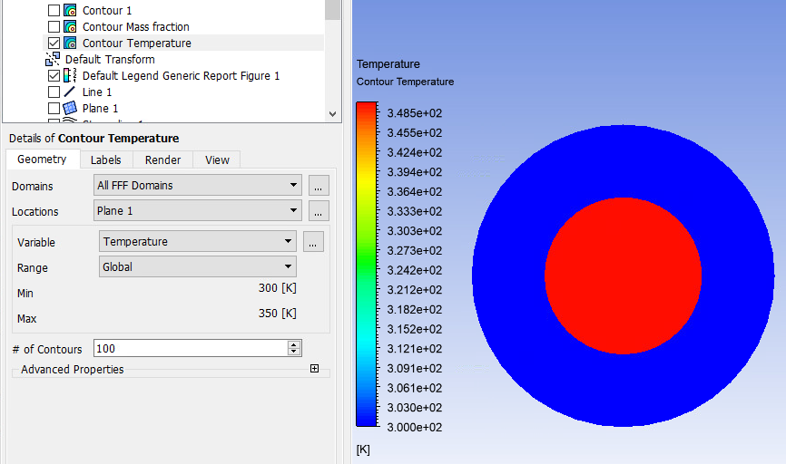
If I can ask you one more question: I would like to visualize the conduction/convection mechanism along the pipe, but I don't understand how to correctly impose the boundary conditions.- Currently, I have selected a water mass flow rate and a T (350 K) for the inlet BC and the following BC for the inner pipe_outerwall and for the wall_fluid domain, respectively:
- With these conditions (initialization of temperature field at 300 K) I have obtained the following output for T and clearly I have neither a temperature gradient, nor a melting process of the PCM (which should start to liquefy at 328 K).
Therefore, my question is: how could I set the problem where I would send a certain flow rate of hot fluid (water) into the inner pipe and see how this exchanges heat with the PCM confined externally in the concentric tubes?Could be the error related to the "solid" definition of the two pipes, not allowing the display of heat exchange?Many thanks in advance!Best regards,
Elisa Revello
-
- The topic ‘Simulation of a Phase Change Material within concentric pipes’ is closed to new replies.


-
4683
-
1565
-
1386
-
1242
-
1021

© 2025 Copyright ANSYS, Inc. All rights reserved.

