-
-
January 8, 2019 at 7:22 pm
goldersantu
SubscriberHello Everyone,
I'm doing heat transfer simulation. A box is contained with steam, the box is also covered with two solid materials. Each material has certain thickness around 20 mm and those are contacting each other. While I did simulation it seems at the contact face of two solid material not working. How can I fix this problem?
Note: I modeled and meshed in ANSYS.
Thanks,
Santu
-
January 8, 2019 at 7:57 pm
Amine Ben Hadj Ali
Ansys EmployeeCan you please add some more information about the solver used and details regarding the simulations? Please add images as many as you can.
-
January 8, 2019 at 8:41 pm
goldersantu
SubscriberPlease see the following picture. The picture has all information. I've monitored inside wood wall temperature. The temperature should be changed but it showed constant till the end of time.
Â
-
January 8, 2019 at 9:04 pm
Amine Ben Hadj Ali
Ansys EmployeePlease use the insert image tool. As ANSYS Stuff I cannot download attachments.
-
January 8, 2019 at 9:06 pm
-
January 8, 2019 at 9:12 pm
Amine Ben Hadj Ali
Ansys Employee
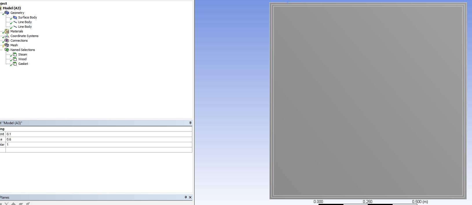
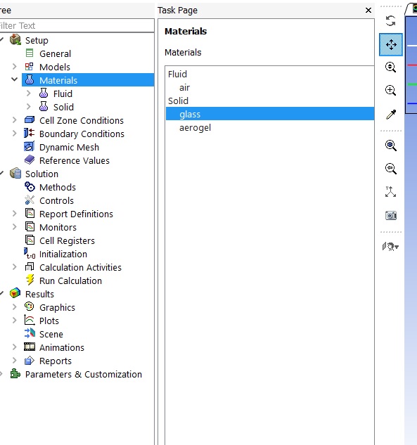
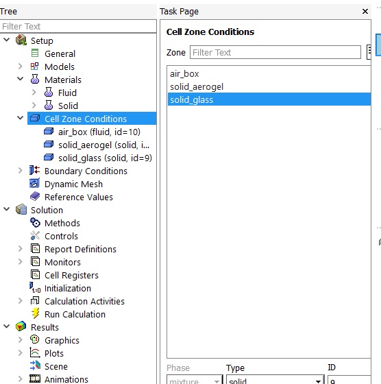
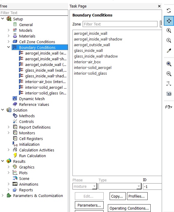
So you have a conformal mesh with three zones. Which Solver are you now using: Fluent, CFX? Please attach screenshots of the boundary conditions in the Solver? How does the Solver interpret the contact walls between the different zones?
Â
I recommend to create named selections for the edge lines separating steam and wood, and wood and the other outer zone, give it name and then transfer to the Solver. ANSYS Fluent for example will create for it, a wall/wall-shadow wall pair.
-
January 8, 2019 at 9:23 pm
goldersantu
SubscriberHello Amine,
I'm using fluent. If you have any tutorial please give me.Â
I modeled in ANSYS design modeler and meshed in ANSYS. Now I'm trying to solve in FLUENT. Mainly the interface wall of two solid wall is not talking each other.
-
January 8, 2019 at 9:25 pm
Amine Ben Hadj Ali
Ansys EmployeeI recommend to create named selections for the edge lines separating steam and wood, and wood and the other outer zone, give it name and then transfer to the Solver. ANSYS Fluent for example will create for it, a wall/wall-shadow wall pair.
Add a screenshot out of ANSYS Fluent on the problematic boundary.
-
January 8, 2019 at 9:30 pm
goldersantu
SubscriberI created name with the edges lines for each wall i.e. Outside wall and inside wall for each zone and run the simulation for an hour (time step). But the temperature is not changing still constant at the inner wall of the box.
-
January 8, 2019 at 9:35 pm
Amine Ben Hadj Ali
Ansys EmployeeThen please share with us all screenshots describing the deployed boundaries in ANSYS Fluent.
-
January 8, 2019 at 9:39 pm
goldersantu
SubscriberOk, I'll create it and share with you as soon as possible. I'll create air instead of steam and two different solid material.
-
January 8, 2019 at 9:40 pm
Amine Ben Hadj Ali
Ansys EmployeeDo not forget to use Ideal Gas Law as EOS for air or Steam.
-
January 8, 2019 at 9:49 pm
goldersantu
SubscriberFor meshing do I've to create "Form new part " in design modeler ?
-
January 8, 2019 at 10:00 pm
Amine Ben Hadj Ali
Ansys EmployeeYes to have a multibody part (single part containing the three sub-parts) to get a conformal mesh. Otherwise, you will get a non-conformal mesh which is okay but might complicate the things a bit as you are a beginner.
-
January 8, 2019 at 10:24 pm
goldersantu
SubscriberCan you share your email address I could send you my file.
-
January 8, 2019 at 10:33 pm
Amine Ben Hadj Ali
Ansys EmployeeAs ANSYS Stuff my assistance is limited to this community. Just insert the screenshot so that we can have a look into your setup.
-
January 8, 2019 at 11:17 pm
-
January 8, 2019 at 11:37 pm
-
January 8, 2019 at 11:41 pm
goldersantu
SubscriberAfter overlapping failure of mesh I defined center wall is a solid aerogel wall as shown in the figure of boundary condition. Temperature is constant as you see at the end of picture. Aerogel outside wall temperature was defined 295 K. The temperature of the inside glass wall should be changed but remained constant.
-
January 9, 2019 at 12:08 am
goldersantu
SubscriberIt seems at the contacting face of two solid material heat is not transferring. Can you tell me how can I fix this.
-
January 9, 2019 at 7:12 am
Amine Ben Hadj Ali
Ansys EmployeeThat means you do not have anymore the mesh failure?
Can you make a contour plot of temperature or make facet average along the wall instead of vertex average?
Please run for more time as diffusion in solid require a lot of time (that is why we usually use a "pseudo" time scale based on the thermal diffusivity. Moreover please go to the Flux Report and make a Total Heat Transfer Report which will tell us if there is heat transfer or not.
Â
-
January 9, 2019 at 10:58 pm
-
January 10, 2019 at 7:10 am
Amine Ben Hadj Ali
Ansys EmployeeWhat are the boundary conditions in the fluid domain? What is the boundary condition for the outer wall (aerogel outside wall)? What does the Flux Report tell you?
-
January 15, 2019 at 8:29 pm
goldersantu
SubscriberI've solved this problem. Thank you.
-
April 9, 2019 at 1:01 pm
ankit5821
SubscriberPlease tell me how you solved it. I have a similar problem -
April 9, 2019 at 1:02 pm
ankit5821
Subscriberplease tell how, I have a similar problem
-
- The topic ‘Heat transfer among Fluid Solid Solid’ is closed to new replies.
- How do I get my hands on Ansys Rocky DEM
- Non-Intersected faces found for matching interface periodic-walls
- Unburnt Hydrocarbons contour in ANSYS FORTE for sector mesh
- Help: About the expression of turbulent viscosity in Realizable k-e model
- Script Error
- Facing trouble regarding setting up boundary conditions for SOEC Modeling
- convergence issue for transonic flow
- Running ANSYS Fluent on a HPC Cluster
- Point exception in erosion calculation
- Errors with multi-connected bodies using AQWA
-
1942
-
865
-
599
-
591
-
366
© 2025 Copyright ANSYS, Inc. All rights reserved.