-
-
October 16, 2023 at 5:18 pm
Kunal Chopra
SubscriberI need to move this wall between two different fluid domains. It can't be interior. So, I am providing UDF motion by DEFINE_CG_MOTION to both wall and wall_shadow. However, after a few time steps, I can see that the wall remains fixed there, while the layer below it keeps getting wider. Also, the wall with adjacent third zone is modelled as deforming and also the side walls of these cylinders. Is it right or is there any other way to move this wall sandwiched between two zones? Kindly, provide help.
-
October 17, 2023 at 2:51 pm
Federico
Ansys EmployeeCan you provide more details/screenshots of how you have set up your dynamic mesh zones?
I'll make some assumptions based on what I see:3 cell zones: grey is solid, blue and green are fluids
The grey zone is initially in contact with both fluid volumes boundaries at the solid's right-most face, where there is a wall/shadow pair.Dynamic Meshing cannot handle changing topology, so if part of the grey wall is not initially inside the fluid domains (blue and green), Fluent will not allow this motion and only the wall/shadow pair (which is already in contact with the fluid volumes) will move.
-
October 17, 2023 at 3:28 pm
Kunal Chopra
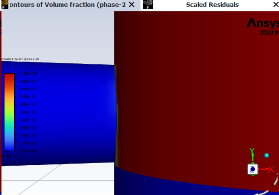
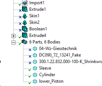
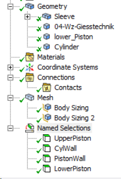
SubscriberThankyou for the reply, the grey part is also fluid and fluid from blue body moves inside the grey pipe whereas the green part goes down gradually so that more and more fluid can enter the grey pipe. I have attached more images of fluid entry zone.
It is working fine uptill mesh distorts in the cylinder-pipe interior as shown in my seperate message in this thread.
-
-
October 17, 2023 at 3:23 pm
-
October 20, 2023 at 3:05 pm
Federico
Ansys EmployeeYou will need to create mesh interfaces so that the blue/green boundary can move independently from this green interior zone. In other words, the green interior should remain a disk, even as the intersecting boundary moves. Am I understanding this correctly?
-
October 20, 2023 at 3:09 pm
Kunal Chopra
SubscriberYes, you are right in saying that one side of it has to move, while the other has to remain fixed but then material also needs to move into the fixed boundary accordingly. How would I do that with mesh interfaces?
-
-
October 20, 2023 at 6:00 pm
Federico
Ansys Employee(Using the colors from your first post) set the blue boundary as single face zone of type wall (including the portion that overlaps with the grey cell zone). Do the same for the green section.
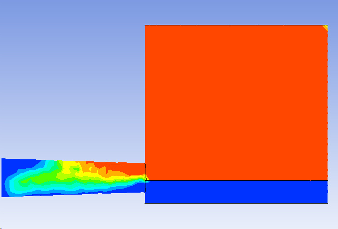
For example, in my dummy case, it looks like this (removing the grey cell zone on the right picture)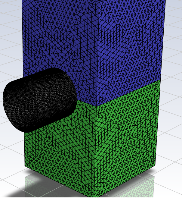
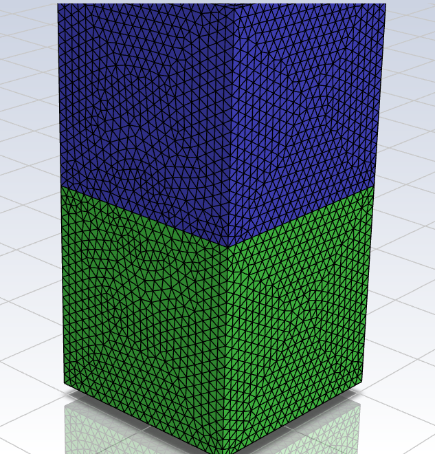
As said above, the green and blue face zones that you see are of type Wall.
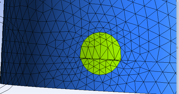
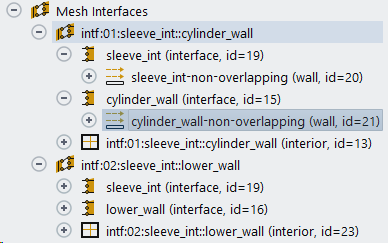
When I create 2 mesh interfaces between the blue and grey zones, and the green and grey zones I get the following:
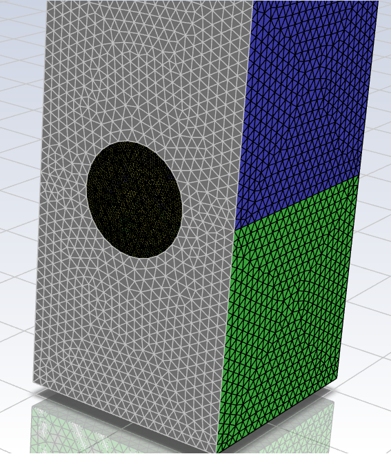
where the overlapping regions of the mesh interface are automatically changed to interior type (disk in the middle) and the non-overlapping regions remain of type wall (shown here in grey).
Now set the boundary between grey and blue zones to move, set the the blue and green walls to deform and you're good to go.
-
October 21, 2023 at 8:01 pm
Kunal Chopra
SubscriberThankyou Federiko for taking so much time to explain in detail. But, I do not have cuboids but cylinders in both blue and green zones. Yes, the interfaces are changed to interior automatically and the rest is wall. I had set the wall to move using the following UDF:
#include "udf.h"DEFINE_CG_MOTION(piston_upper, dt, vel, omega, time, dtime){real t = CURRENT_TIME;NV_S(vel, =, 0.0);if (t <= 0.05){vel[1] = -1.5;}else{vel[1] = 0.0;}}Are you suggesting that I set the whole interior region between blue and grey to motion? And also, its the udf given to wall between blue and green zone, so green-grey zone interior has to basically convert to blue-grey zone as fluid is in blue zone that has to enter the pipe.-
October 23, 2023 at 12:58 pm
Federico
Ansys EmployeeThere is no difference if your case is made up of cylinders or cubes.
There is only 1 boundary moving, that's the one separating blue and green zones. The sides boundaries should be set to deforming.
-
October 23, 2023 at 6:04 pm
Kunal Chopra
SubscriberWhich is exactly what I did. I set the side boundaries as deforming while the one seperating blue and green is moving down but as you can see in the images that I posted, the upper part of the deforming mesh i.e. elements in the wall between blue and green keeps stretching while the ones in the wall between green and grey keeps compressing but they do not collapse and ultimate I get the error of negtive cell volume.
-
October 23, 2023 at 6:25 pm
-
-
-
November 6, 2023 at 5:32 pm
-
November 7, 2023 at 1:54 pm
Federico
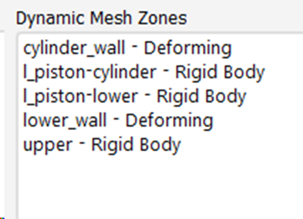
Ansys EmployeeCan you show your DM zones?
-
November 7, 2023 at 6:25 pm
-
November 7, 2023 at 8:49 pm
-
November 14, 2023 at 11:50 pm
Kunal Chopra
SubscriberHi Federico,
Do zou have any suggestions on how to solve this problem?
-
November 15, 2023 at 1:13 pm
Federico
Ansys EmployeeI gave you all the information that I can.
As asked previously, can you show me your Dynamic Mesh zones?
-
-
November 15, 2023 at 9:29 pm
-
November 17, 2023 at 2:10 pm
Federico
Ansys EmployeeNot sure what any of these zones are.
-
-
- The topic ‘UDF for moving a wall’ is closed to new replies.


-
4683
-
1565
-
1386
-
1242
-
1021

© 2025 Copyright ANSYS, Inc. All rights reserved.


