-
-
June 6, 2021 at 10:51 am
Lillo
SubscriberHello
I think I have an error on the calculation of the reaction force due to the contact between two bodies.
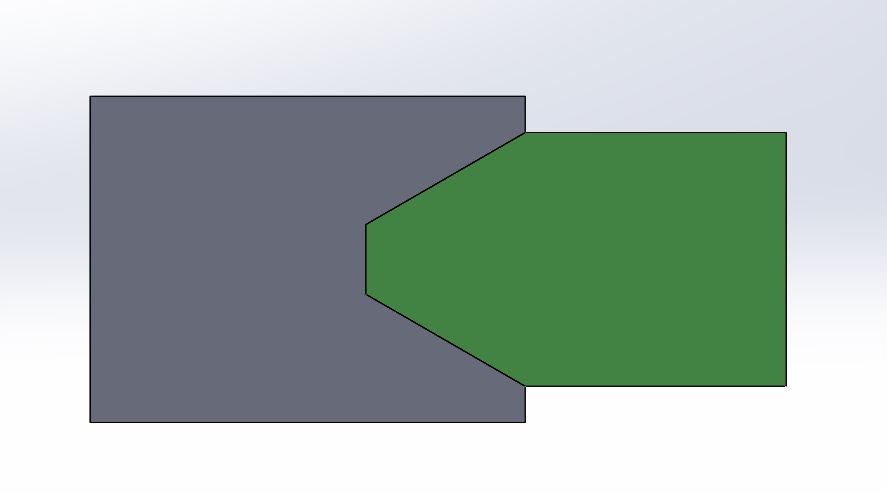
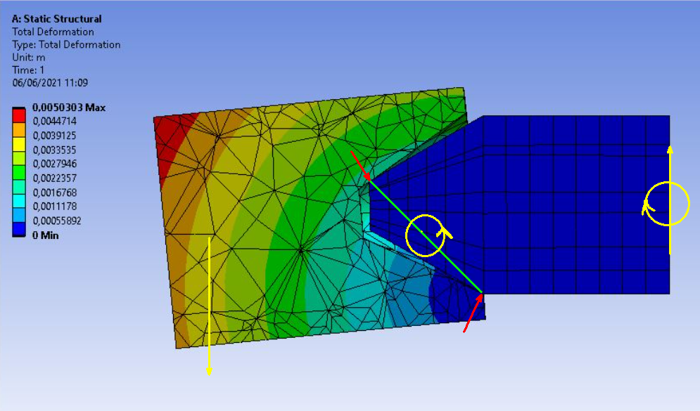
As you can see from the figures I have a conical pin inserted in a special slot. At the end of the pin there is a fixed support, while at the end of the slot there is a point mass that simulates the weight of a shaft and what is mounted on it. This shaft is supported at both ends by two conical pins (in the simulation I considered only one pin, halving the weight of the mass to be supported).
The contact constraint was assigned as follows:
- type of contact = friction
- conical pin = contact
- slot = target
- friction coeff = 0.7 (steel vs steel)
- behavior = symmetric
At this point, by checking the reaction force, I get that all the weight (2700 N) has been discharged in the Z direction. But shouldn't there also be a substantial thrust component in the Y direction?
I have also attached my hand calculations, so as to show you my reasoning.
Do you think there is an error in the hand calculations or is the FEM modeling to be wrong?
June 6, 2021 at 1:53 pmpeteroznewman
SubscriberI think there is an error in your hand calculation.
The model does not have a single point of contact, but two points of contact. Take those two points and compute the normal force at each end. Because of the short distance along Y (or X') between the two points and the the distance to the point mass, the reaction force on the bottom is much greater than m.g so maybe the shaft is not sliding but sticking. If the shaft is sticking, there will be no thrust.
June 6, 2021 at 3:30 pmLillo
SubscriberI see! Thank you very much for your reply and for having highlighted this criticality. I may have found the solution to the problem of possible shaft slippage without even wanting to.
Also, I would like to take the opportunity to quickly ask a couple of other questions:
1) Why is the pin completely undeformed? Is there an error or do you think it could be physically accurate? If it is an error how can I fix it? Using bounded contact instead of friction?
2) How could I improve the mesh of the target body? The automatic methods are not applicable so I need an alternative strategy
June 7, 2021 at 9:29 amChinmay
Subscriber
I may not be an expert but I have following observations:
First of all, awesome & clear explanation of problem from your side.
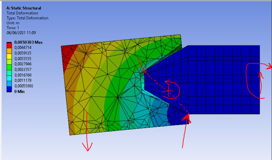 As rightly suggested by Peter, there are two points of contacts; and that should create a moment which is countered by the fixed support.
Considering this as cantilever problem (sorry not a block on a wedge problem, although you did solve it correctly; not useful in this case) When we do force equilibrium, we get reaction Fz = mg which it should show and no initial force in Y direction will give reaction Fy = 0 N as shown by software.
But because there is two point contact, it should give a moment as shown in poorly drawn art work above but there should be a reaction moment too at fixed support in my opinion (and not force in Y direction).
1) Why is the pin completely undeformed? Is there an error or do you think it could be physically accurate? If it is an error how can I fix it? Using bounded contact instead of friction?
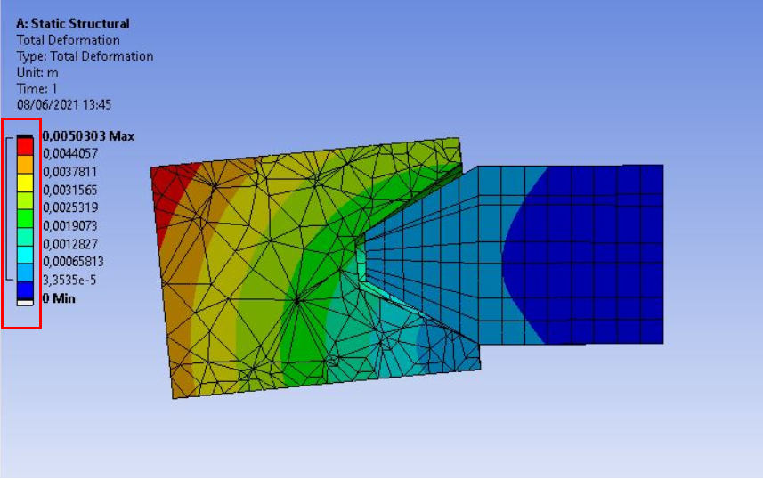
--> Bonded contact wont give realistic result (It should ideally slip from the conical surface). Now, what I think reason for no deformation in conical pin is that, You either made it rigid body (which is not the case here because you cannot cut rigid body using section plane tool in result) or maybe because the length of the pin is considerably short compared to distance of point mass to conical pin or the deflection is very less compared to other deflection, maybe try scaling the result, adding (+) more color pallet in the result and check ?
2) How could I improve the mesh of the target body? The automatic methods are not applicable so I need an alternative strategy
--> Check if it is a sweepable body or not (mesh--> show -- show sweepable bodies), if it is, go for sweep method with manual target and contact faces if not I would suggest method of hex dom) for better mesh.
Or manually, reduce the element size if you want to. I don't understand "automatic methods are not applicable" statement.
Thanks Chinmay
June 7, 2021 at 11:59 amLillo
SubscriberFirst of all, thank you very much for your reply and for the compliment for my exposition of the problem
But because there is two point contact, it should give a moment as shown in poorly drawn art work above but there should be a reaction moment too at fixed support in my opinion (and not force in Y direction).
I checked and there is indeed a moment of reaction to the fixed support. But I wonder if the forces in the two points of contact don't really develop forces in the Y direction. It must be a strange coincidence because with inclined surfaces you would expect a thrust force in the Y direction due to the wedge effect
maybe try scaling the result, adding (+) more color pallet in the result and check ?
Thank you! I have scaled the results and in fact now see a gradient of coloring. The deformation were indeed very small
I don't understand "automatic methods are not applicable" statement.
I meant that I have already tried all the automatic methods without success (sweep, multizone, hex dom, mapped, etc). I just have to try some more sophisticated approach, but I'm not sure how to do it
June 8, 2021 at 4:11 amChinmay
Subscriber
Good that you got the moment reaction at the fixed support. That is how the equilibrium equations work. Yes you are thinking right, with inclined surface there is a force in two directions, Like a block sliding on a wedge, for low frictional coefficient, it will move wedge too. But again that's for single point contact. If there are two point of contacts, what do you think it will do to the wedge ?
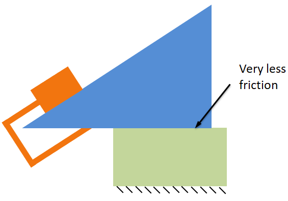 Instead of pushing it, it will try to topple it with a moment. And then this moment is countered by the fixed support in your case. (This is for low friction case, in your case, the friction is sufficient to hold on to the pin)
 I am glad adding color pallet and scaling the result helped you to determine if there is deflection in conical pin or not. Kindly share results if possible.
Are you trying out these mesh methods for conical pin or the special shaped shaft ? Kindly elaborate on what exactly do you wish to do here, unless you got the desired results.
June 8, 2021 at 12:50 pmLillo
SubscriberThank you very much for the explanation. It all makes sense now!
I am glad adding color pallet and scaling the result helped you to determine if there is deflection in conical pin or not. Kindly share results if possible.
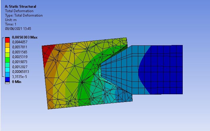 As you can see we are talking about really small deformations
Are you trying out these mesh methods for conical pin or the special shaped shaft ? Kindly elaborate on what exactly do you wish to do here, unless you got the desired results.
I'm trying out these mesh methods for the special-shaped shaft.
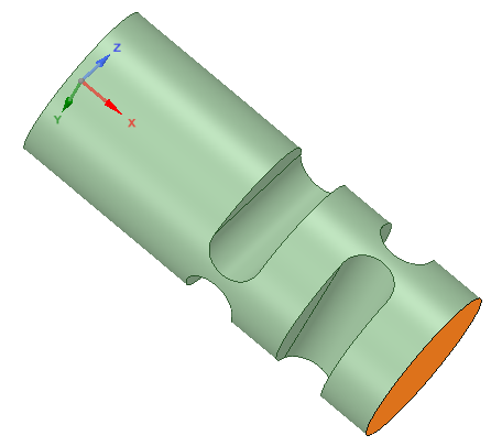
Actually, this is only a first attempt at analysis, so perhaps improving the mesh at this stage is not that important. The true geometry of the pin and shaft are as follows:
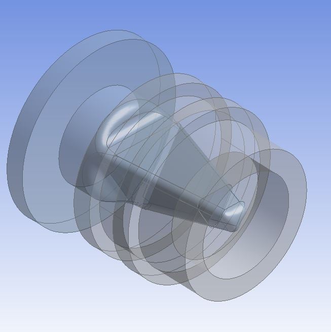
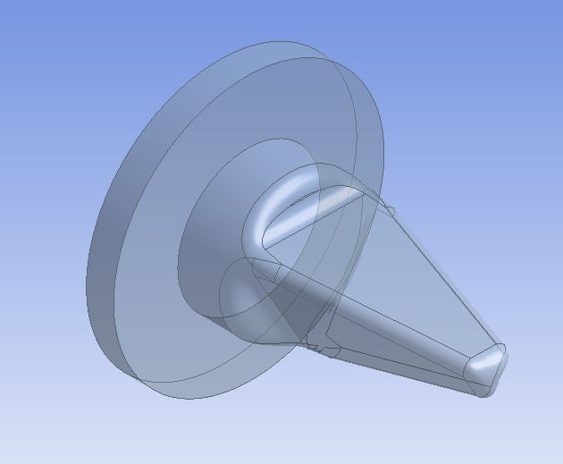
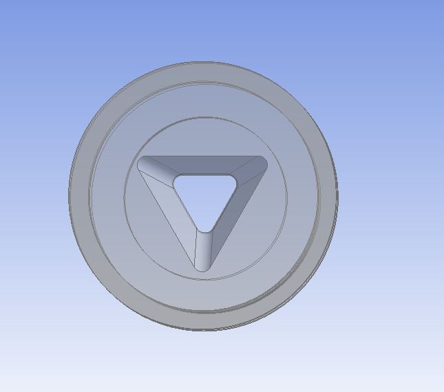
As you can see in the following images, I also make the same settings for the analysis on the real geometry by adding a frictionless support so as not to have the cantilever beam (which I think was an error in the previous modeling).
Basically, my goal is to calculate the axial thrust that is applied to the fixed support. This is because in the real application there isn't a fixed support but the pin is held in position by an external force. I couldn't replicate this condition in the static structural simulation environment because the model would have been under-constrained.
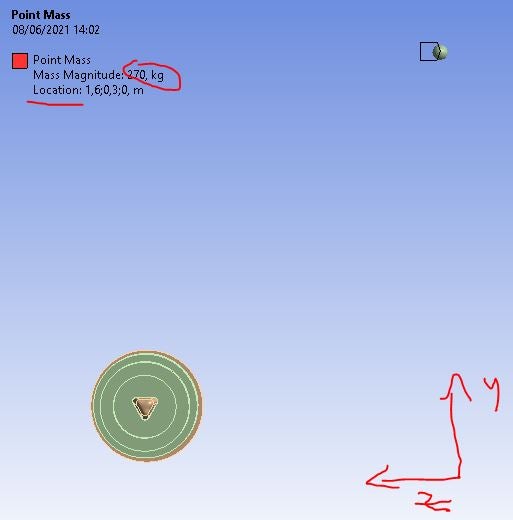
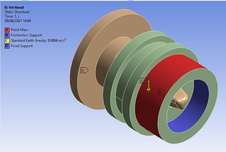
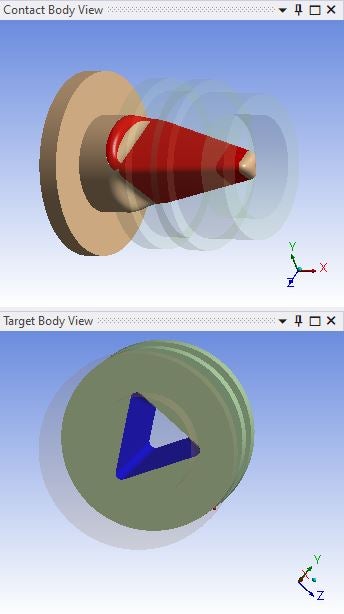
However, after your explanation, it occurred to me that the sticking effect on the two contact points could be used to prevent too much force from being discharged axially on the pin. Obviously, this effect is not desired when inserting the pin, so I don't know if it is actually a good thing to continue to explore this path or is better simply analyze the system to determine the force necessary to hold the pin inside its seat in the shaft (which was the initial goal of this analysis). What do you think about it?
June 9, 2021 at 4:29 amChinmay
Subscriber
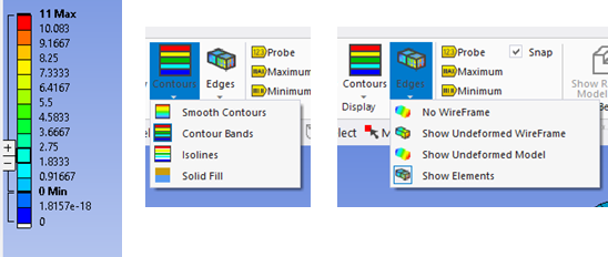
By adding (+) in color palette I meant, adding more colors gradients to the existing palette Ansys offers by default.
 You probably already know this, but when you hover over the colors highlighted above you see (+ & -) on left side, just press + till you see more color gradients. This improves understanding of the solution for me. Try different options like show contours or bands to see more variations or maybe 'drag aqua color band down towards 0'. Isolines help a lot too.
 Coming back to your problem
Looking at the changes you made with your support, I have few follow-up questions if you don't mind.
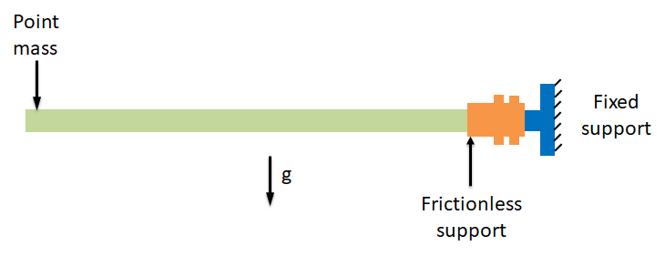
 1) I am wondering where exactly is Point mass located. (If it is shown in Red color in left fig, exactly over frictionless support or is it same as you previously mentioned, quite far away from fixed support.
2) As you said, not a cantilever now, how are you hoping to load the pin structure ? (Probably as shown below, if not kindly elaborate please )
If simply supported then it would act like
 If radially supported as shown in figure above then it would act like
 Maybe, I am thinking something quite different than it actually is.
--> I couldn't replicate this condition in the static structural simulation environment because the model would have been under-constrained.
Can you please tell what condition is it ? Maybe we could try together to figure it out using various remote displacement options or something else ? Its better to get results with conditions as close as possible to real conditions.
--> What do you think about it?
I could comment on it after I understand the exact problem, sorry if I wasn't much helpful here.
Thanks Chinmay.
June 9, 2021 at 6:15 pmLillo
Subscriber
first of all thank you so much for your kind help and patience
You probably already know this, but when you hover over the colors highlighted above you see (+ & -) on left side, just press + till you see more color gradients. This improves understanding of the solution for me. Try different options like show contours or bands to see more variations or maybe 'drag aqua color band down towards 0'. Isolines help a lot too.
Actually, I had forgotten about this function. I will treasure this advice from now on!
1) I am wondering where exactly is Point mass located. (If it is shown in Red color in left fig, exactly over frictionless support or is it same as you previously mentioned, quite far away from fixed support.
The point mass is located quite far away from fixed support. The part highlighted in red on the shaft is where I decided to apply the load due to that mass. Basically, it is equivalent to applying a remote force. Or am I doing something wrong?
 2) As you said, not a cantilever now, how are you hoping to load the pin structure ?
Perhaps the case of "simply supported beam" could be more truthful, but I'm not completely sure. Now I try to explain better what the problem consists of, so maybe you can give me some advice about it
Can you please tell what condition is it ?
My problem consists in dimensioning the shaft and the support system of an automatic positioner (similar to that for welding by robot) on which a workpiece is keyed and that must be worked according to different angular positions (in fact I think that I should add to the model also the centrifugal force due to the rotation of the point mass).
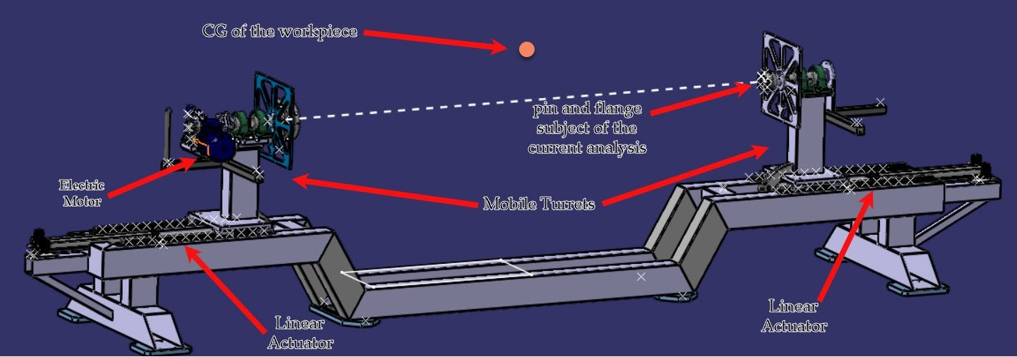
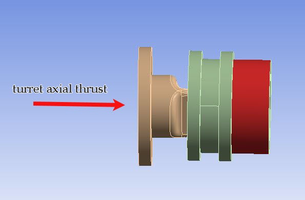
As you can see from the figure (or at least I hope you can see it) there are two pins mounted on two mobile turrets that have the task of supporting and transmitting the rotary motion to the workpiece. Therefore, as previously mentioned, in reality the pins are not constrained in the direction of the rotation axis and are held in position by an axial force exerted by a linear actuator placed at the base of the mobile turrets and which counteracts the axial reaction thrust that the specially-shaped shaft exercises on the two pins.
To simplify the analysis, I decided to exploit the symmetry of the problem and therefore to analyze only one of the two shaft-pin couplings, thus halving the value in kg of the point mass.
In addition, I have tried to constrain the problem as it is in reality but, working in "static structural", the model is under-constrained and unsolvable. Because of this, I replaced the thrust force exerted by the linear actuator with a fixed support. In this way, going to check what the value of the constraint reaction in the axial direction is, I can calculate what the thrust that my linear actuator must supply to the turret must be to avoid the disengagement of the shaft.
I hope the problem is clearer now. If not, do not hesitate to let me know and I will try to provide you with further details.
Thanks again for the help!
June 10, 2021 at 5:05 amChinmay
Subscriber
Thank you for sharing your actual problem statement. Now that I understand your problem quite clearly, I think I can contribute better.
As seen from the figure above, I notice that this pin and shaft (PS) system is going to rotate with the help of electric motor, now my question is:
1) If the WP is rotating continuously or just momentarily till you rotate it by a small angle ?
2) Also the shaft in your PS system seems like a flange or a coupling between the Pin and the WP (to transfer rotation from motor to pin to WP) ? Or is the shaft part of the WP which is mounted over the pin with the help of linear actuators ?
_______
For first case, continuous rotation of WP: (a bit complicated but we can solve it with discussion)
I notice that the CG of the workpiece (WP) is not co-axially aligned with the PS system and I hope you have done or will be doing fatigue effect because of the centrifugal force (as you correctly mentioned) on your PS system which is going to be major concern in my opinion (Also assuming its a balanced WP system, if its unbalanced you will have to balance it before doing fatigue analysis or calculations which ever you prefer)
For second case, rotation of WP by small angle: (Easier of the two cases)
If the angles are fixed, do a static loading at 90┬░ rotation (which is worst case scenario in my opinion).
______
I agree with what you did to simplify the problem, symmetry and halving the load is right, but it can be simplified further.
I feel like yours is a static case and then centrifugal force need not be worried about. You can transfer the Weight force (F=mg) from CG to WP end of the shaft. All you have to do is shift it parallel and add the moment at the WP end of the shaft to make it statically equivalent system.
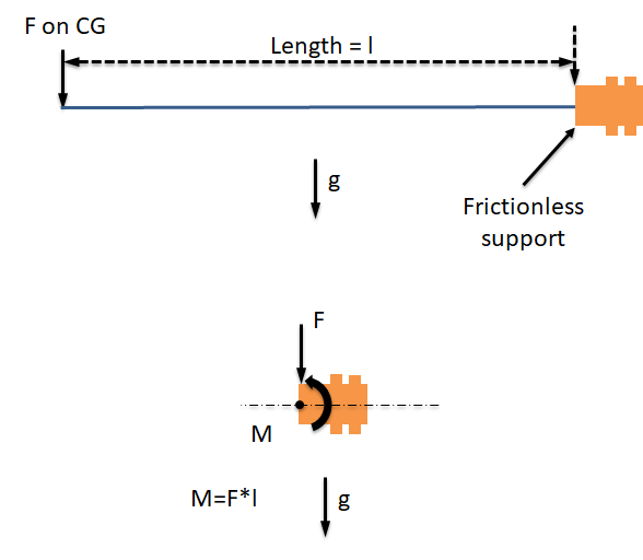 So basically your focus is to design a holding mechanism for the WP and rotate it by some angle to work on WP maybe. I still think there won't be an axial thrust on the base of the turrets, unless you bring the actuators very close that the WP is applying force on the top end of the turret via the Pin (IDK if this explanation is clear or not) All you actually need to worry about is the moment (which is also a kind of force on turret base if you think about it)
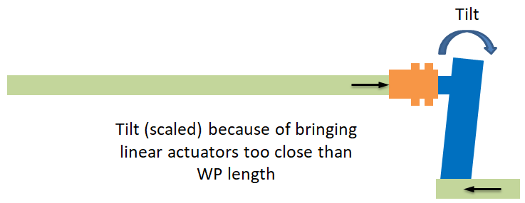 Kindly let me know, if my understanding is in line, if not, please correct me.
Mention which case are we talking about and we can discuss further (I hope this isn't very urgent considering we can contact only once a day, probably because of the time difference.)
June 10, 2021 at 8:46 pmLillo
Subscriber
don't worry about the response time due to the time zone. Having the opportunity to talk to you on a daily basis, even if only once a day, is already a great help! But thanks for your concern As seen from the figure above, I notice that this pin and shaft (PS) system is going to rotate with the help of electric motor, now my question is:
1) If the WP is rotating continuously or just momentarily till you rotate it by a small angle?
Let's say it is more the second case. The WP will have to rotate until it sequentially reaches four desired positions with an increment of rotation of 90 ┬░ with respect to each other. The WP must be worked by a laser in all four positions that will follow. Consequently, the service of the electric motor will be of the intermittent type with running phases (rotation of 90 ┬░) and stop to allow processing (which can last even a few minutes) which are repeated alternately until a full revolution is completed.
2) Also the shaft in your PS system seems like a flange or a coupling between the Pin and the WP (to transfer rotation from motor to pin to WP) ? Or is the shaft part of the WP which is mounted over the pin with the help of linear actuators ?
Yes, itÔÇÖs the first one you said. As you have rightly noted "the shaft" acts as a flange to connect the real rotation shaft (which is an integrated part of the WP) to the pin, to transfer rotation from motor to pin to WP.
(Also assuming its a balanced WP system, if its unbalanced you will have to balance it before doing fatigue analysis or calculations which ever you prefer)
What do you mean when you talk about balanced / unbalanced system? I thought that to conduct an analysis in the "static structural" environment the system had to be necessarily balanced. Otherwise it would not be solvable. Or is there something I'm missing?
Also in the second case, that of intermittent rotation with 90 ┬░ angles, should I still carry out a fatigue analysis of the PS system? Or would the effect of fatigue be negligible in this case?
If the angles are fixed, do a static loading at 90┬░ rotation (which is worst case scenario in my opinion).
Yes, the angular rotations are fixed, and even I actually thought of considering the most disadvantaged case the one with static load at 90 ┬░ (i.e. when the moment arm is at its maximum)
I feel like yours is a static case and then centrifugal force need not be worried about. You can transfer the Weight force (F=mg) from CG to WP end of the shaft. All you have to do is shift it parallel and add the moment at the WP end of the shaft to make it statically equivalent system.
I have a question about this simplification of the problem. If I eliminate the point mass, how can I then insert the centrifugal force in the model?
I also have a practical question. When do you say that I have to add the moment at the WP end of the shaft, at what point of the shaft are you referring to in particular? In other words, which area should I select as the area of application of the moment? The more external surface of the shaft / flange?
So basically your focus is to design a holding mechanism for the WP and rotate it by some angle to work on WP maybe
Exactly, I have to design a holding and centering mechanism for the WP and rotate it by some angle
So basically your focus is to design a holding mechanism for the WP and rotate it by some angle to work on WP maybe. I still think there won't be an axial thrust on the base of the turrets, unless you bring the actuators very close that the WP is applying force on the top end of the turret via the Pin (IDK if this explanation is clear or not) All you actually need to worry about is the moment (which is also a kind of force on turret base if you think about it)
Actually, a first prototype of the system has already been built and, through empirical observation, I can tell you that if the turrets are not held in position by the actuation force of the linear actuators placed at their base, they tend to be pushed away by the shaft which therefore tends to slide off the two pins.
However, this axial force that we are experimenting empirically, could actually be due to the presence of the tilting moment you are talking about.
Also, could you be so kind as to explain to me what you mean by the following sentence? :
"I still think there won't be an axial thrust on the base of the turrets, unless you bring the actuators very close that the WP is applying force on the top end of the turret via the Pin"
June 11, 2021 at 7:32 amChinmay
Subscriber
Sorry for delayed response, got caught up at work and thank you for clearing the problem statement.
The service of the electric motor will be of the intermittent type
That's good !! Easier of the 2 cases.
What do you mean when you talk about balanced / unbalanced system?
You need not worry about balancing WP system, that was for Dynamic analysis Case 1.
Also in the second case, that of intermittent rotation with 90 ┬░ angles, should I still carry out a fatigue analysis of the PS system? Or would the effect of fatigue be negligible in this case?
I do think Fatigue analysis is not required even though the PS system will be in alternate tension and compression in 360┬░cycle (at least not initially).
Yes, the angular rotations are fixed, and even I actually thought of considering the most disadvantaged case the one with static load at 90 ┬░ (i.e. when the moment arm is at its maximum)
Doing 1 case is not sufficient is what I think, because the PS system is going to be in tension and compression alternately, thus I was wondering if we could solve this problem in 4 steps with CG of the WP (along with PS system) changing its location by 90┬░ rotation in every step.
I have a question about this simplification of the problem. If I eliminate the point mass, how can I then insert the centrifugal force in the model?
So for intermittent rotation we can consider your problem statement under static loading and no need to consider centrifugal force effect (I am assuming the angular velocity is very low thus high torque).
I also have a practical question. When do you say that I have to add the moment at the WP end of the shaft, at what point of the shaft are you referring to in particular? In other words, which area should I select as the area of application of the moment? The more external surface of the shaft / flange?
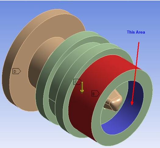 The highlighted are is where the WP shaft fits right ? That's where that shaft will apply moment (Force) on PS system.
Also what I would have done is considered WP shaft, then PS system, turret and linear actuators simultaneously with WP shaft, Linear actuators as Rigid bodies while everything else as flexible body with BC's as Fixed support at Actuator base, Pin fixed to Top of Turret (I saw that there are bearings housings which are mounted on top of the turret) and so on if you are interested because then you would directly get stresses developed in Turrets and load at the actuator base. Also I think there should be ribs supporting the turret and minimize the tilt avoiding slippage of shaft from PS system.
I have another question, is the design of Pin confirmed and cannot be changed ? I was thinking about it last night and I thought a squared shape pin (and not tapered) with a considerable entry chamfer at the WP end of shaft would make a better pin design, avoiding slipping, reducing tilting of Turrets and increasing overall strength of this structure. (if the diameter of pin is more than 25mm then we can go for hexagonal shaped pin too)
Thanks Chinmay
June 11, 2021 at 5:23 pmLillo
Subscriber
don't worry about the delay, and thank you for your time!
Doing 1 case is not sufficient is what I think, because the PS system is going to be in tension and compression alternately, thus I was wondering if we could solve this problem in 4 steps with CG of the WP (along with PS system) changing its location by 90┬░ rotation in every step.
Yes, the PS system will alternately be in tension and compression but in module the quantities of the stresses will be the same, or Is there something I'm missing?
In any case, if I want to do a 4-step analysis, do you think it is necessary to conduct four different analyses, or is it possible to do everything within a single structural analysis by changing the settings within the various steps? If the latter case is what you suggested, how do I rotate the model from one step to another? Or is it enough to set four different concentrated forces and moments rotated 90 ┬░ to each other and then individually activated during the various steps of the analysis?
So for intermittent rotation we can consider your problem statement under static loading and no need to consider centrifugal force effect (I am assuming the angular velocity is very low thus high torque)
Yes, through a dynamic calculation I estimated a torque of about 1500 Nm and an angular speed of about 6 rpm (very low indeed).
Okay then, I'll omit the centrifugal force if you think it might be negligible in this case.
The highlighted are is where the WP shaft fits right ? That's where that shaft will apply moment (Force) on PS system.
I see! Thanks for the clarification
Also what I would have done is considered WP shaft, then PS system, turret and linear actuators simultaneously with WP shaft, Linear actuators as Rigid bodies while everything else as flexible body with BC's as Fixed support at Actuator base, Pin fixed to Top of Turret (I saw that there are bearings housings which are mounted on top of the turret) and so on if you are interested because then you would directly get stresses developed in Turrets and load at the actuator base.
Actually, I could try to do as you said. My only concern is that an analysis of this type would be much more complex to complete and at this moment the geometries are not yet fully defined (so I risk "wasting time" and then having to repeat it all over again).
In this phase, a rough sizing based on the PS system alone may be sufficient, I suppose. Or do you think I should follow your suggested approach anyway?
Also I think there should be ribs supporting the turret and minimize the tilt avoiding slippage of shaft from PS system.
I honestly hadn't considered this hypothesis. With bare eye I don't see such deformation as to justify the sliding of the shaft on the pin. Consequently, I thought that this phenomenon was due purely to the principle of the inclined plane.
I will try to take this into account as well then
I have another question, is the design of Pin confirmed and cannot be changed ? I was thinking about it last night and I thought a squared shape pin (and not tapered) with a considerable entry chamfer at the WP end of shaft would make a better pin design, avoiding slipping, reducing tilting of Turrets and increasing overall strength of this structure. (if the diameter of pin is more than 25mm then we can go for hexagonal shaped pin too)
No, the design of the pin is still ongoing and undergoes changes on a practically daily basis.
Could you kindly explain your idea better? Maybe with a little sketch?
In any case, the current pin has been conceived as conical because the WP is placed in the center of the positioner with a small angular misalignment with respect to the axis of rotation of the motor (misalignment due to the non-centesimal precision of the hydraulic motor that must lift the WP). Consequently, the two pins placed on the turrets not only have the task of supporting the weight of the WP and putting it in rotation, but also that of centering it with respect to the axis of rotation of the motor. A conical type coupling should certainly be self-centering. I don't know how a pin of a different shape could behave instead. My fear is that there may be jamming due to the initial misalignment between the shaft axis and the axis of the pin attached to the turret
June 12, 2021 at 4:54 ampeteroznewman
Subscriberand The design of the pin is what I would call a tetrahedron. If that tetrahedron was pushed into a fitting that had three fixed sphere, that would constrain 3 Degrees of Freedom (DOF).
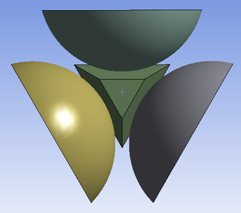 I'm not recommending this design, I'm just providing some food for thought. This configuration has the effect of a soft spring to prevent rotation. The much better design is the tetrahedral pin that goes into a matching tetrahedral pocket as you have shown, and such a configuration is like a very stiff spring to prevent rotation.
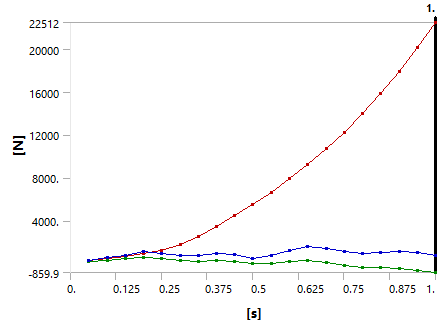
For frictionless contact of the three spheres on the three flats, there is no torque to prevent the first increment of rotation, but as the contact point moves along the plane, the flat faces of the pin move their contact point off center and develop a contact force. Consider the case where the other end of the shaft is fixed and the pin is inserted into a 3-sphere pocket that rotates about the shaft axis. Now as the rotation increases, an axial force develops to push the pin out of the 3-sphere pocket.
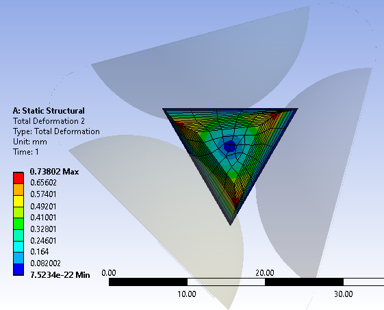 The axial reaction force as a function of rotation is shown below.
 June 13, 2021 at 8:39 am
Lillo
SubscriberThank you for your time and for sharing your thoughts about my problem.
So, a tetrahedral shape of the pin indeed generates an axial thrust which pushes the pin out of its slot in the shaft. Do you think a truncated conical shape of the pin (like the one shown in my first post) could reduce this effect? Obviously then I should find an additional way to constrain the rotation between the crankshaft and the WP and then transmit the torque to the shaft of the WP
June 13, 2021 at 12:19 pmpeteroznewman
SubscriberThe benefit of using tapers is that all the clearance is removed, which is very important when rotating the workpiece (WP) in precise 90 degree increments. The cost is to ensure the design provides an axial force that exceeds the cam-out axial force generated by the pin. I used a 5 degree taper angle in my example. A 2 degree taper would generate less axial force but the pockets might need to be deeper and retract more to accept a longer pin, which would be needed to maintain the same misalignment tolerance to get the pin in the hole. As long as the linear actuators on the ends can generate a force that exceeds the axial reaction force of the pins, that is an acceptable condition to have in the design.
There are collars that clamp onto a cylindrical shaft, which when tightened, also have a clearance-free connection to the shaft. That is more difficult to implement in a machine that is being designed for automated WP loading, which is an objective of the current design.
I'm also thinking about the fact that the Center of Gravity (CG) of the WP is off the axis of rotation. I suggest you characterize the rotational stiffness of the interface between the features on the shaft end and the receiving features on the end of the machine that has the motor that rotates the WP. It looks like the opposite end of the machine has just a bearing to allow free rotation. That means all the torque generated by the radius of the CG from the shaft axis must be reacted by the features at one end only. If you know the stiffness of the interface, you can apply the maximum moment and determine the angle of rotation of the shaft. Now look at the maximum distance on the WP from the axis to see if the displacement of that point on the WP has an acceptable deviation due to the flexibility of the coupling. If not, you will need to look for an alternative coupling design that would have much higher angular stiffness than a tetrahedral pin in a tetrahedral hole.
June 13, 2021 at 3:31 pmLillo
SubscriberThank you very much for the clarification. However, I had two questions following your explanation (sorry if they may seem silly):
1) How can I determine the relationship between the taper angle and the misalignment tolerance necessary to allow the pin to enter the hole? In other words, is it possible to perform a parametric study (maybe in Ansys itself) to understand how much I can push with the reduction of the taper angle in order to reduce the axial thrust?
2) If I understand correctly you are suggesting me to check that the deformation in the circumferential direction Y (measured on the surface of the coupling between shaft and flange) does not exceed the positioning accuracy tolerance required for my application. Correct?
June 13, 2021 at 5:50 pmpeteroznewman
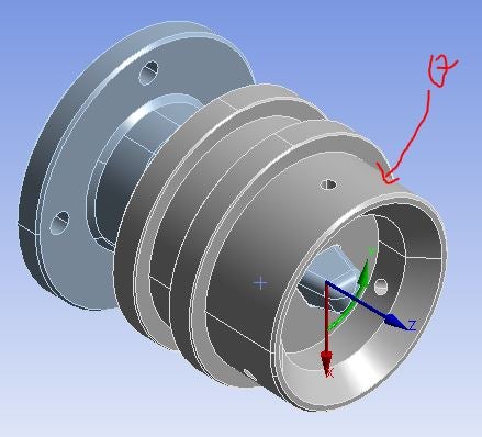
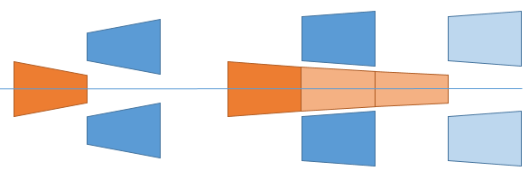
SubscriberThe figure below illustrates that the reduction in taper angle can be compensated for by using a pin that is three times longer while maintaining the same misalignment tolerance on the error between the hole centerline and the pin centerline when the face of the pin reaches the face the hole is in.
Use the maximum torque on the pin from the CG being off axis and use an FEA model to solve for the angle of rotation A (radians). Now if the largest radius of an important feature on the WP is R (mm) then that feature will move tangentially R*A (mm) from where it is expected to be for a perfectly rigid coupling. In addition to that, there is the gravity sag of the WP added to that movement. Consider that when the WP is rotated 180 degrees, the feature moves in the opposite direction by that same R*A and the gravity sag also reverses.
June 13, 2021 at 7:21 pmpeteroznewman
SubscriberThe vertical distance between the corner of the face of the pin and the corner of the face of the hole is the misalignment tolerance. If the alignment is within that distance, then the pin goes in the hole. If the alignment is outside that distance, then the pin face crashes into the face of the part with the hole in it. The misalignment tolerance is reduced when the taper angle is reduce if the axial travel is the same. Adding pin length and axial travel can increase the misalignment tolerance.
 June 14, 2021 at 9:29 pm
Lillo
Subscriberand I wanted to update you on the status of my problem. As you can see from the pictures below the design of the coupling between the pin and flange on the shaft has changed a lot.
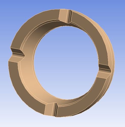
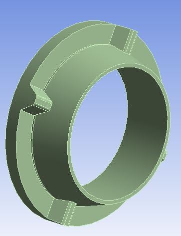
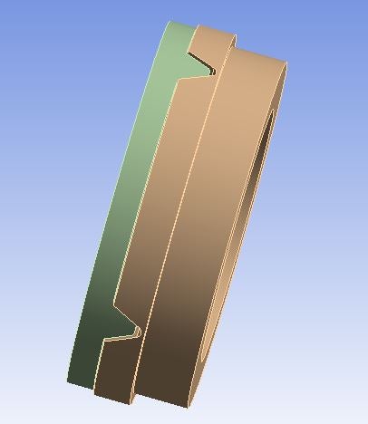
As you can see from the figures below, following the advice of I further simplified the model by replacing the point mass that represented the CG of the WP (and on which the force of gravity was acting), with a moment and a force concentrated on the flange. All the other settings are the same.
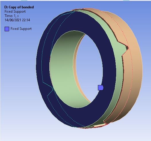
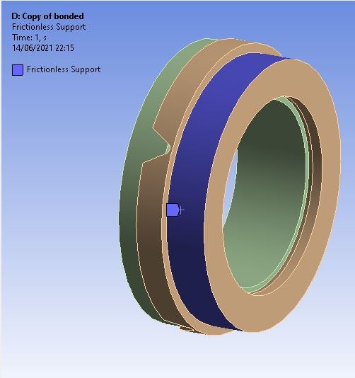
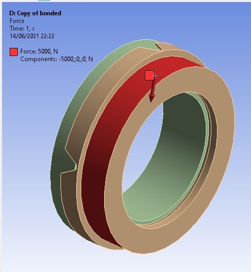
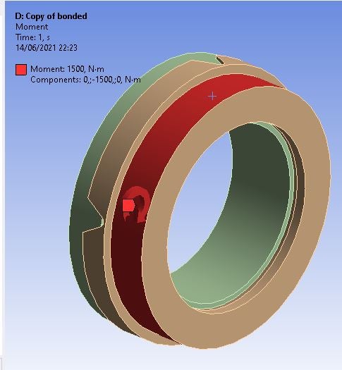
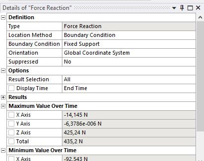
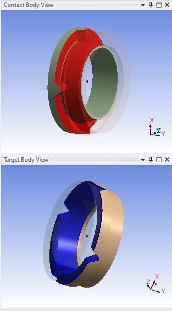 However, going to solve the model, I noticed a possible inconsistency. The total reaction of the moment evaluated to the fixed support is 1500 Nm, exactly like the moment I applied to the flange; on the other hand, the total reaction force is much less than the 5000 N applied by me. In your opinion, what could be the reason for this discrepancy?
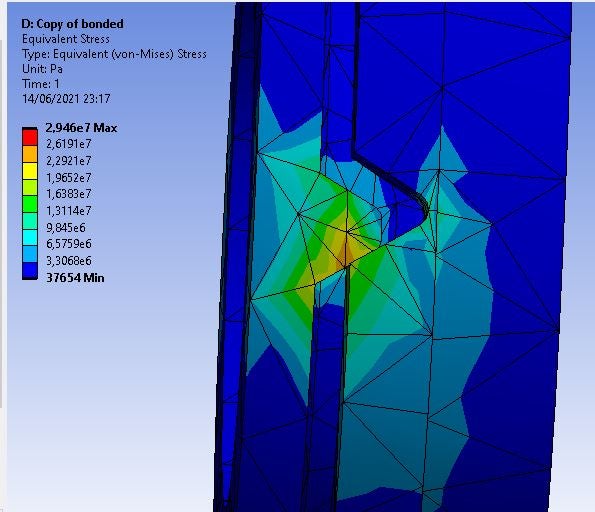
In addition, I would like to ask you if you think it is appropriate to improve the mesh and, if so, what strategy I could adopt to achieve the purpose
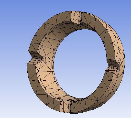
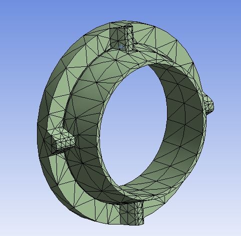
Thanks to both of you for your kind help
June 14, 2021 at 10:55 pmpeteroznewman
SubscriberThis is indeed an improvement over a tetrahedral pin.
This reminds me of an Exact Constraint coupling between two bodies which consists of three V-shaped channels that accept three spheres. Since the three spheres make contact with six planes, that constrains exactly six DOF. If you delete one of the four features and reposition the three remaining features at 120 degrees around the circle, that is what I am thinking of.
However, the other end of the shaft constrains 2 DOF so that connection is over-constrained.
June 21, 2021 at 5:00 pmLillo
SubscriberThanks for your comment
So you think I'm on the right track. I'm glad! Now I'll try to make a geometry with three elements equally spaced at 120 ┬░
Is the fact that the system is over-constrained a problem? I believe that it makes everything more stable, otherwise I would basically have a cantilever beam, whose deflection at the free end reduces the accuracy of the positioning of the system
June 22, 2021 at 4:16 ampeteroznewman
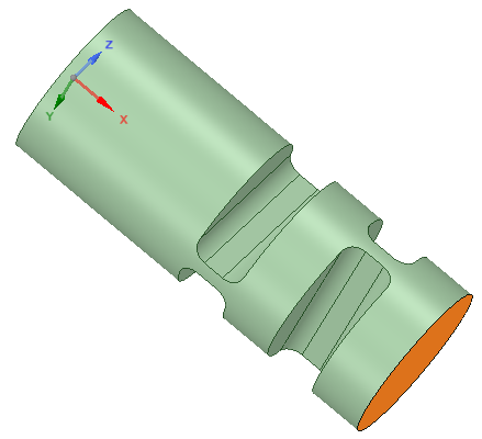
SubscriberThe system is only overconstrained if all the bodies are rigid. It's okay if there is compliance and the WP may be considered the compliant member.
If the WP is very rigid, then you can design in compliance in the two DOF that are overconstrained.
One example is two flexures at 90 degrees. The orange face would have the three Vee slots that I haven't drawn. The two flexures allow the orange face to rotate about Y and Z axes so that the other end of the WP can align with the connection at that end.
June 22, 2021 at 12:00 pmJune 22, 2021 at 7:28 pmLillo
SubscriberThank you so much for the original suggestion! I hadn't thought at all about this type of design!
Viewing 24 reply threads- The topic ‘Possible error in the reaction force due to the simulation of contact between two bodies’ is closed to new replies.
Innovation SpaceTrending discussionsTop Contributors-
4618
-
1530
-
1386
-
1209
-
1021
Top Rated Tags© 2025 Copyright ANSYS, Inc. All rights reserved.
Ansys does not support the usage of unauthorized Ansys software. Please visit www.ansys.com to obtain an official distribution.
-


Ansys Assistant

Welcome to Ansys Assistant!
An AI-based virtual assistant for active Ansys Academic Customers. Please login using your university issued email address.
Hey there, you are quite inquisitive! You have hit your hourly question limit. Please retry after '10' minutes. For questions, please reach out to ansyslearn@ansys.com.
RETRY
