3D Wing Geometry Creation (optional)
Note: If you wish to skip this topic, click "complete" on the top right of the page.
This airfoil file was created to mimic the geometry used by NASA in their CFD. First, everything was scaled down according to their scaling factor and we switched the units from meters to feet for ease. We then needed to calculate the root chord which was possible due to the knowledge of the taper ratio. We also needed to change the thickness from the scaled values that were provided to match with the NASA geometry. With some additional manipulation, we get the .txt airfoil file given below.
The airfoil file contains the coordinates of the root chord according to how we calculated the NASA geometry. There are three columns, (x,y,z) with the z column being all 0. The coordinates start at (0,0,0) and trace the coordinates to the length of the airfoil with 0 thickness at the trailing edge and then these coordinates are traced back to (0,0,0) to create a closed curve, which is required by Solidworks.
The airfoil file that was created can be downloaded here: Download
- Open a new Solidworks Part
- Change units so that length scale is in feet
- Navigate to the Features Tool Bar and select Curves → Curves through X Y Z Points:

- Browse to where you have saved the airfoil .txt file (you will need to change the file type for which Solidworks is searching)
- Click OK
- You should see an image similar to the one below:
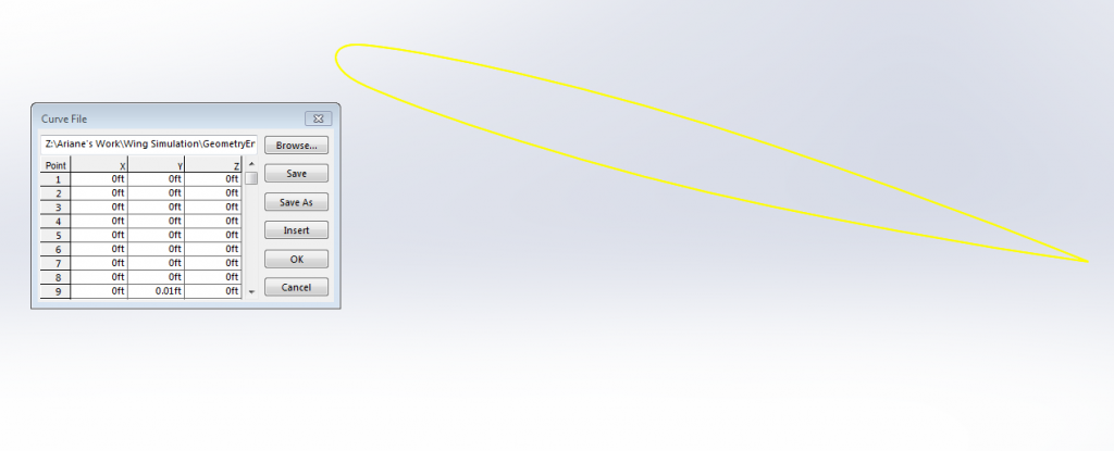
- Select the Front Plane → New Sketch
- Select Convert Entities:

- Select the airfoil as the entity to convert
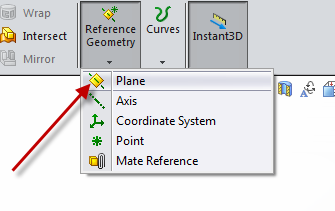
- Create a new plane
- In the Details Panel, select the Front Plane as the First Reference and set the Distance to 1 foot. (This is because our wing-half span is 1 foot)
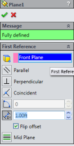
- Create New Sketch
- Select the plane you just created
- Select Convert Entities
- Select the airfoil to convert. See the image below for reference:
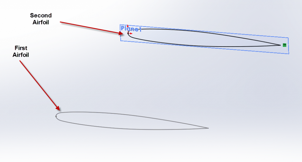
- Scale the second airfoil: Move Entities→Scale Entities
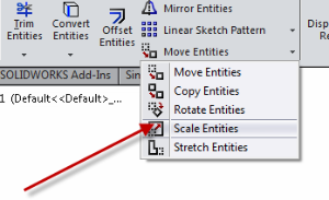
- Scale Factor: .562 (This is the taper ratio of the wing, defined a the ratio of the tip chord to the root chord)
- The point to scale about will be origin (this is the origin point of the second airfoil)
- Move Entities: (See the above image)
- Select the second airfoil
- Duplicate the image below in your details window:
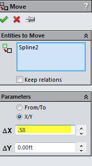
The change in x here is from the wing geometry described on NASA's website. Since the leading edge angle of the wing is 30 degrees and we know the span to be 1 foot we can calculate the change of the tip chord x in relation to the location of the root chord. - Create a new sketch on the Top Plane
- Select Line and connect the origin from the root airfoil to the origin of the tip airfoil and make sure they are coincident with the line.
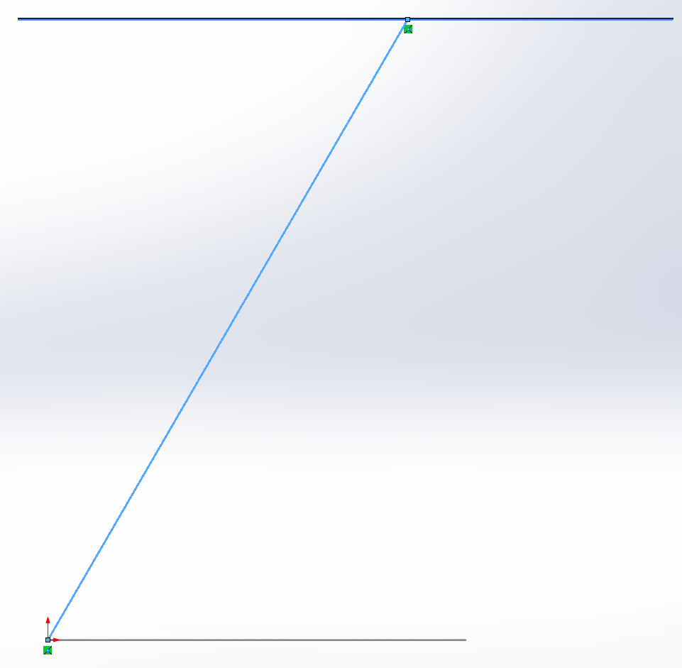
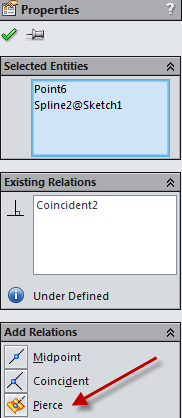
- In the same sketch a new line and connect the airfoils via the trailing edge. You will need to use the pierce condition to make sure the line is connected with the airfoils.
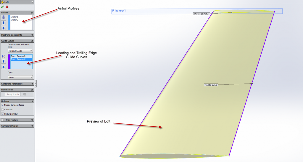
- In the Features Toolbar go to Lofted Boss/Base
- Select the two airfoil sketches as the profiles
- Select the two lines (leading and trailing edges) as the guide curves
- Make sure the preview matches what you are expecting
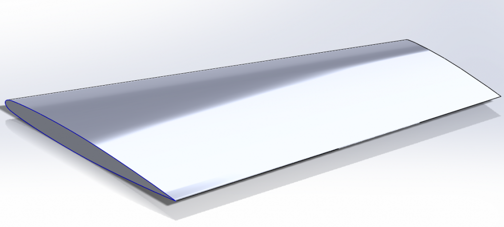
- Click the green checkmark and you have created the wing geometry!

