-
-
July 30, 2024 at 7:37 am
 SolutionParticipant
This article is part of an embedded Human Machine Interface (HMI) design blog series. It details the process of designing a next generation embedded HMI for the control of an industrial steam boiler and implementing it with Ansys SCADE. You can find links to each part below:
- Part 1 – Designing a next-gen embedded HMI
- Part 2 – Implementing a next-gen HMI in SCADE Display
- Part 3 – Powering a next-gen HMI with SCADE Suite
- Part 4 – Integrating a next-gen HMI onto a hardware target
Introduction
This article presents an overview of the integration of a SCADE-developed HMI for an industrial steam boiler onto a realistic hardware target.
The steam boiler is like the one you’d find in a nuclear power plant. It uses a heat source (e.g. nuclear fuel) to produce steam. It is controlled by a reactive control loop that balances sensor readings (temperature, steam pressure, water level) within acceptable parameters by using actuators (water injection valves).
In our previous article, we used SCADE Display to implement the HMI panel and SCADE Suite for the panel behavior. We will now use the SCADE certified code generators to generate C code from our models. We’ll then embed it onto a hardware target.
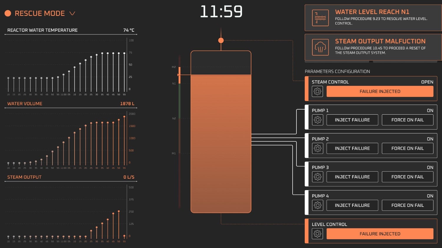
As a reminder, here is what our graphical panel looks like:

Overview of our HMI panel in rescue modeHardware target
In the world of safety-critical applications, application code usually runs on specialized technological platforms. Hardware tends to be ruggedized to resist adverse conditions: vibration, wide temperature ranges or even harsh radiation. CPUs may use reduced instruction set (RISC) architectures instead of the ubiquitous x86 architecture found in desktops and laptops. Operating systems tend to be real-time (RTOS), as the timely computation of results matters as much as the results themselves.
In our case, we will be using two distinct environments:
- Our development machine is a laptop with an Intel Core-i7 x86-64 CPU and an RTX A2000 GPU, running Windows 11.
- Our Smart Boiler hardware is an i.MX 8 board with an ARM Cortex-A53 CPU and a GC7000 GPU, running a Linux OS. We will be using an external display screen connected to the board via an HDMI connector.
Code generation in SCADE
SCADE relies on qualified code generators to generate safe, embeddable, platform-independent C code. Let’s unpack this:
- The code is safe because the Scade language avoids many categories of bugs by construction (e.g. uninitialized memory access), and because our KCG code generator is qualified to the highest levels of safety with key safety standards (such as DO-178C, ISO26262, EN50128 or IEC 61508).
- The code is embeddable because it’s ready to be compiled and executed on various hardware platforms without modification. For SCADE Display graphical panels, the target just needs to support some flavor of OpenGL.
- The code is platform-independent because no system calls are made in it. Aside from drawing calls for graphical panel code, there are no I/Os, no filesystem interaction, no dynamic memory allocation, no networking. Interaction with the outside world (e.g. through input devices) is managed by reading/writing pre-allocated structures.
Code Integration
Running a program built with SCADE Display & SCADE Suite requires a small integration layer that performs the program’s initialization phase. This code performs the following activities:
- Allocate a known, static amount of memory for the program
- Create and initialize structures that will be used by the generated code
- Initialize display drivers
- Initialize input devices
- Call the model’s entry-point operator.
For real-time operating systems that use a task scheduler, integration code must create and launch a task to run the SCADE model’s main operator.
SCADE Suite includes wrappers for Windows host and a selection of widely-used embedded targets. These wrappers automatically generate the integration code as part of the push-button build from the SCADE Display IDE.
Graphics drivers
SCADE Display supports many flavors of OpenGL (vanilla, ES, SC) in different versions. Each one has a slightly different API shape: the embedded and safety-critical flavors offer less functions. To accommodate this, SCADE relies on a middleware library called OGLX.
In practice, this is the flow of drawing calls in a SCADE Display program:
Drawing call flow for a SCADE Display programSGL is a higher-level interface provided for graphical calls by OGLX. They allow the SCADE program to speak a “common language” that can then be adapted by the library into calls in the corresponding OpenGL flavor.
OGLX is written in C. Its source code is certifiable to the highest levels of safety with key safety standards. Sources are delivered with SCADE and must be configured, compiled and linked for the target hardware. This is typically achieved from a Windows host computer with correct parameters for cross-compilation to the desired target.
Compilation pipeline
Overall, the generation and compilation pipeline looks like this:
Overall generation pipeline for a SCADE Suite / SCADE Display programGenerating for Windows host
While developing and testing a SCADE application, engineers need to run it frequently. Since the SCADE IDE runs on Windows, generating code and building it for a Windows host target is a common use case. It is therefore supported as a “push button” activity.
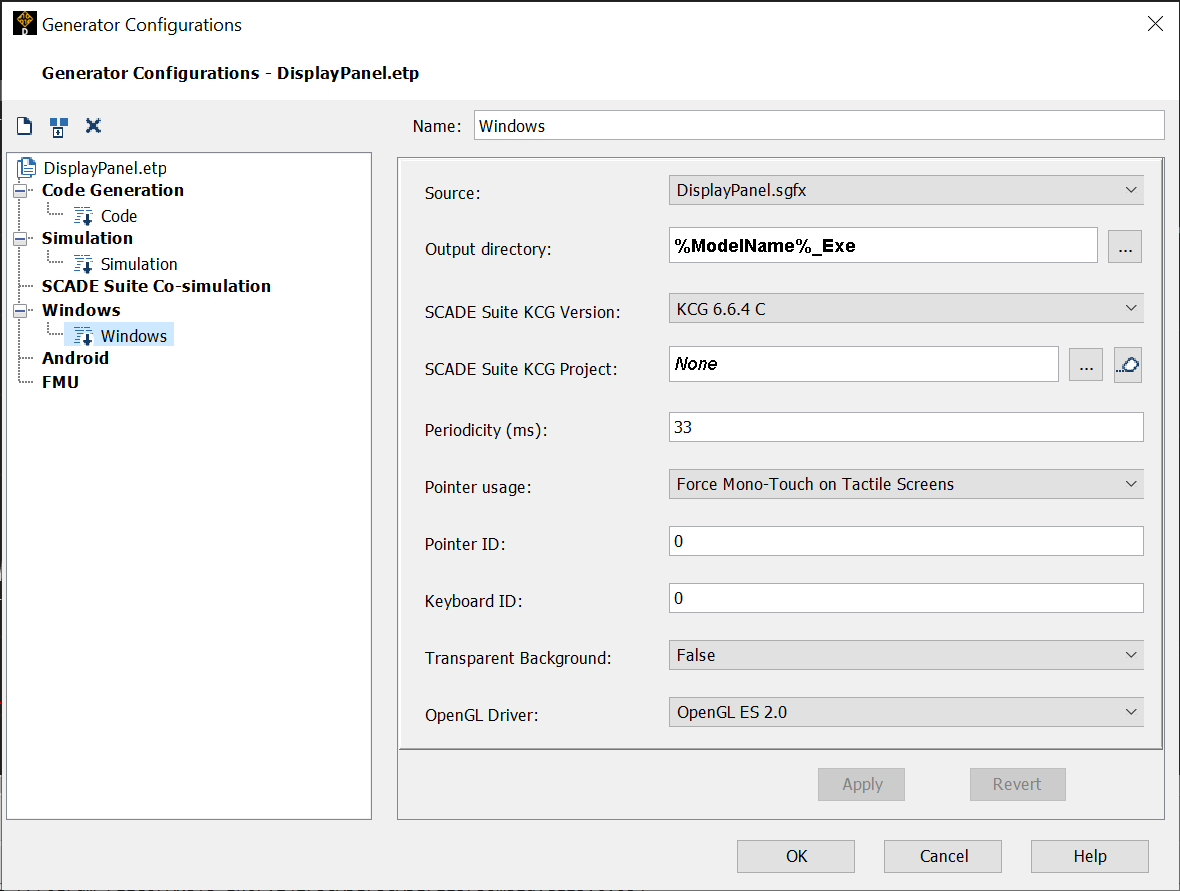
In our Smart Boiler example, the SCADE Display model includes the SCADE Suite model as a library. So, the whole process is triggered from a SCADE Display Generator Configuration.

Windows executable generation configuration in SCADE DisplayThis configuration triggers the whole process: code generation using KCG Display for the Display model and KCG for the Suite model, generation of integration code for a Windows host, compilation and linking of the program for a Windows host, and launch of the finalized program in a new window.
Note: to save time in this case, the OGLX library is precompiled.
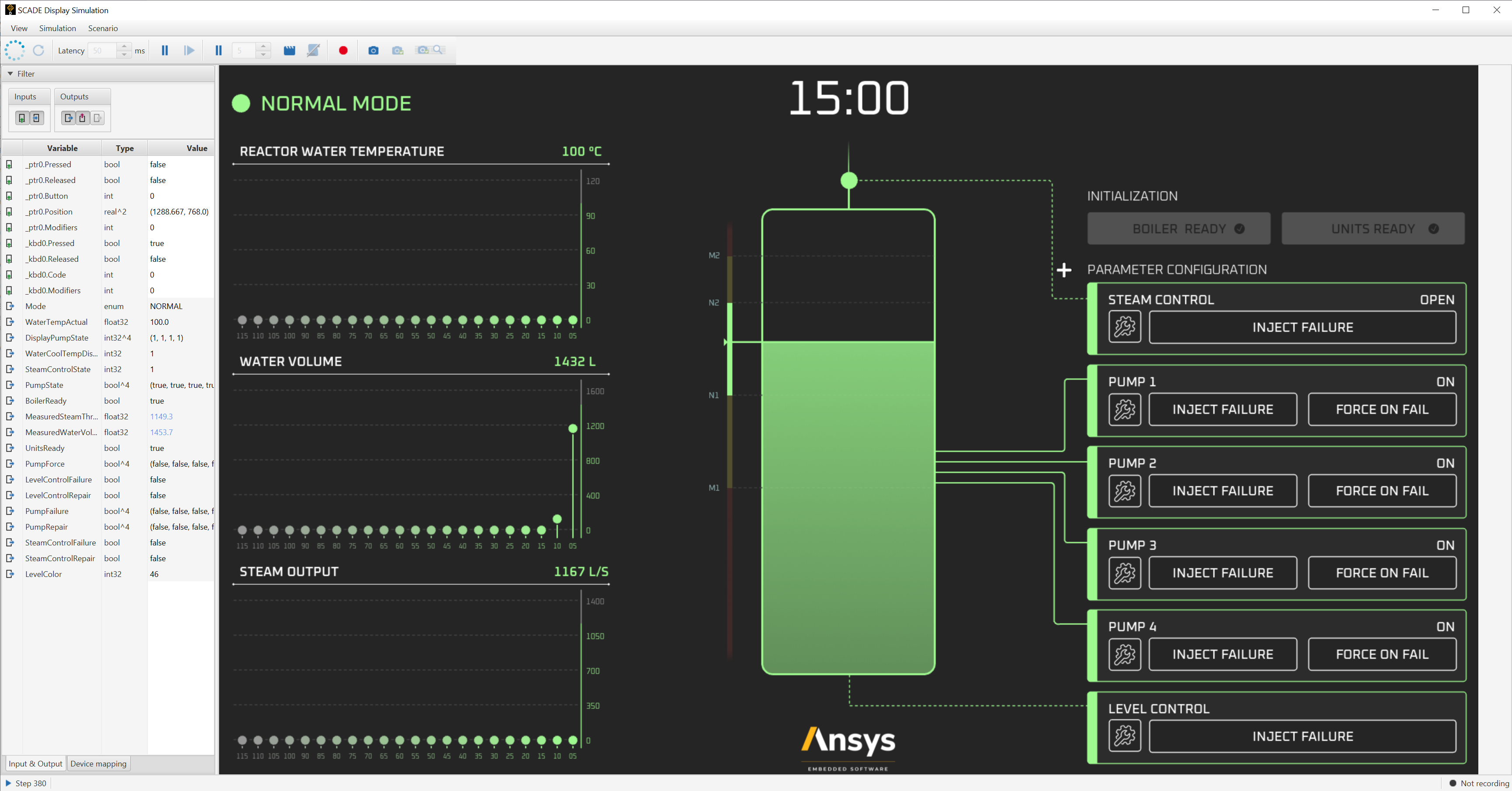
In addition to the Windows generation configuration, you can see above another one called Simulation. This simulation launches the program with debugging enabled. An integrated window allows to run the program at various speeds, pause it, interact with the HMI, and watch underlying variables.

Interactive co-simulation windowGenerating for Linux iMX 8
Now, let’s look at generating the program for its intended embedded target. For our Smart Boiler, we have chosen a widely-used hardware platform:
- Hardware platform: NXP i.MX 8QuadMax MEK
- Graphics: GC7000 – Vivante
- CPU: ARM Cortex-A53
- OS: Yocto Linux 4.14.78
- Graphics Driver: OpenGL SC 2.0 – CoreAVI
- Display: external HDMI screen
We start by launching the Code generation configuration from SCADE Display. This generates C code for the SCADE Display and SCADE Suite models.
OGLX configuration for Linux iMX8
Next, we retrieve the OGLX source code and ready it for cross-compilation via the included
oglx_port.hfile. While the file can be modified to accommodate the desired target, in our case, we can simply rely on one of the pre-included macros to control common target restrictions and build features.Our target has no specific restriction, so we don’t need to define any of the following macros:
/*****************************************************************************************************************
 Specific OGLX porting macro definitions

 Following macros can be defined if the user environment does not provide a feature
     OGLX_NO_VERTEX_ARRAY | Vertex arrays are not provided by the used OpenGL driver
     OGLX_NO_GLCLIPPLANE  | Clip planes are not provided by the used OpenGL driver
     OGLX_NO_64_BITS      | 64 bits integers are not provided by the compiler environment
     OGLX_NO_FTOL2        | Cast between float and 64 bits integers is not provided by the compiler environment
 Following macros can be undefined if the user environment does not provide a feature
     OGLX_FBO             | Static mechanism uses frame buffer objects (To undefine if FBOs are not provided)
     OGLX_DISPLAY_LISTS   | Static mechanism uses display lists (To undefine if display lists are not provided)

*****************************************************************************************************************/
We want to use an OpenGL SC2 driver, so we define the
SC2_DEV_ENVmacro:#elif defined(SC2_DEV_ENV) #include
#define OGLX_FBO #define OGLX_MASK_FFFF 0xFFFF With this single change, we can pre-compile OGLX as a static library (
liboglx.a).Main function for Linux iMX8
We now need to write a
main.cfile to tie everything together.Our main function’s job is to:
- Initialize the display in the correct resolution
- Initialize OGLX and the underlying display driver
- Start an infinite rendering loop to:
- Render the next frame into a hidden graphical buffer
- Swap the hidden and screen buffers to display our new frame
We also elect to start our main function in its own thread, but we will leave details out for simplicity’s sake. Here’s what the code for our main function looks like:
void sampleApp1Thread(void *pHead)
{
    /* Initialize required structures */
    uint32 threadId = *((uint32 *)pHead);
    EGLDisplay *dpy = NULL;
    EGLContext *ctx = NULL;
    EGLConfig *cfg = NULL;
    EGLSurface *sfc = NULL;
    EGLNativeDisplayType *dpyId = NULL;
    EGLBoolean errorStatus = EGL_TRUE;
    GLuint shaderProgram = 0;
    GLint aVertex = 0;
    GLint aVertexColor = 0;
    GLint aTexCoord = 0;
    GLint uTexUnit = 0;
    GLint uRotation = 0;

    dpy = &f_dpy;
    ctx = &f_eglContext;
    cfg = &f_config;
    sfc = &f_surface;

    /* Initialize a display using EGL */
    errorStatus = egl_init(dpy, ctx, cfg, sfc);
    if (EGL_FALSE == errorStatus)
    {
        printf("[SampleApp1:Thread%d] Display failed creation. Aborting\n", threadId);
        return;
    }

    /* Initialize OGLX */
    oglx_init();
    init_scene();

    /* Main loop proper */
    while (TRUE)
    {
        /* Render the next frame into a buffer */
        display_callback();

        /* Swap buffers to display the next frame */
        if (EGL_TRUE != eglSwapBuffers(*dpy, *sfc))
        {
            printf("[SampleApp1] ERROR: eglSwapBuffers() unexpected error rendering to display %d", *((uint32 *)dpy));
        }
    }
}
Now, let’s dive further into interesting details of what happens under the hood.
Create a display using EGL
EGL is a native platform interface that connects the windowing systems to one of Khronos’ APIs, e.g. OpenGL SC 2.
Before getting to OpenGL, we first need to set it up. We will create an EGL render context using OpenGL SC as the client API connecting to the “display”. The term display may sound a bit odd at first if you’re used to Windows. It may be more familiar if you’re coming from Linux.
Let’s look at some key things happening inside of our
egl_init(...)function call above.First, we get a device context from our window and connect it to the EGL display:
    /* Obtain an EGL Display */
    if (EGL_TRUE == errorStatus)
    {
        *dpy = eglGetDisplay((EGLNativeDisplayType)&nativeDisplay);

        if (EGL_NO_DISPLAY == *dpy)
        {
            printf("[SampleApp1] ERROR: Failed to obtain EGL display\n");
            errorStatus = EGL_FALSE;
        }
    }

    /* Initialize EGL */
    if (EGL_TRUE == errorStatus)
    {
        errorStatus = eglInitialize(*dpy, 0, 0);
    }
Then, we select a valid EGL configuration that supports our requested client API and fits our description. This is similar to finding a suitable pixel format for context creation in OpenGL:
static EGLint f_attribs[] = { EGL_BUFFER_SIZE, 32, EGL_DEPTH_SIZE, 16, EGL_SAMPLE_BUFFERS, 1, EGL_SAMPLES, 4, EGL_NONE };
    /* Obtain the first configuration with a buffer size of 32 bits */
    if (EGL_TRUE == errorStatus)
    {
        errorStatus = eglChooseConfig(*dpy, f_attribs, cfg, 1, &numCfgs);
    }
Once we’ve got a valid configuration, we can create a window surface that’ll be used for rendering:
    /* Create an EGL Surface */
    if (EGL_TRUE == errorStatus)
    {
        *sfc = eglCreateWindowSurface(*dpy, *cfg, win, NULL);

        if (EGL_NO_SURFACE == *sfc)
        {
            printf("[SampleApp1] ERROR: Failed to create EGL window surface\n");
            errorStatus = EGL_FALSE;
        }
    }
Getting back to OpenGL terminology, we’re now ready to create our OpenGL SC rendering context:
    /* Create an EGL Context */
    if (EGL_TRUE == errorStatus)
    {
        *ctx = eglCreateContext(*dpy, *cfg, EGL_NO_CONTEXT, NULL);
       // *ctx = eglCreateContext(*dpy, *cfg, EGL_NO_CONTEXT, f_contextAttribs);


        if (EGL_NO_CONTEXT == *ctx)
        {
            printf("[SampleApp1] ERROR: Failed to create EGL context\n");
            errorStatus = EGL_FALSE;
        }
    }
Finally, we need to make our EGL context current:
    /* Make this EGL context current */
    if (EGL_TRUE == errorStatus)
    {
        errorStatus = eglMakeCurrent(*dpy, *sfc, *sfc, *ctx);

        /* Setting swap interval to 1 will rely on vsync */
        eglSwapInterval(*dpy, 1);
    }
Initialize OGLX
We’re almost ready to put something on the screen. We first need to initialize OGLX before rendering in our EGL context:
/*+ FUNCTION DESCRIPTION ----------------------------------------------
    NAME:           oglx_init
    DESCRIPTION:    Complete initialization sequence for OGLX
---------------------------------------------------------------------+*/
void oglx_init()
{
    /* Initialize OGLX */
    static SGLbyte glob_tub_texture_buffer[4 * SGL_TEXTURE_MAX_WIDTH * SGL_TEXTURE_MAX_HEIGHT];
    sgl_texture_attrib *glob_texture_attrib = malloc(sizeof(sgl_texture_attrib) * getTextureTableSize());
    sgl_gradient_attrib *glob_gradient_attrib = malloc(sizeof(sgl_gradient_attrib) * getGradientTableSize());
    static sgl_parameters lParameters;

    lParameters.ul_screen_width = getW();
    lParameters.ul_screen_height = getH();
    lParameters.pb_texture_buffer = glob_tub_texture_buffer;
    lParameters.ul_texture_max_width = SGL_TEXTURE_MAX_WIDTH;
    lParameters.ul_texture_max_height = SGL_TEXTURE_MAX_HEIGHT;
    lParameters.p_texture_attrib = glob_texture_attrib;
    lParameters.ul_number_of_textures = getTextureTableSize();
    lParameters.p_gradient_attrib = glob_gradient_attrib;
    lParameters.ul_number_of_gradients = getGradientTableSize();
    lParameters.ul_binary_format = GL_PROGRAM_BINARY_COREAVI;

    sglInit(&glob_s_context, &lParameters);

    /* Load the color table */
    sglColorPointerf(getColorTable(), getColorTableSize());

    /*sglSetRenderMode(SGL_RAW_OPENGL_LINES);*/

    sglLineWidthPointerf(getLineWidthTable(), getLineWidthTableSize());

    /* Load the line stipple table */
    sglLineStipplePointer(getLineStippleTable(), getLineStippleTableSize());

    /* Load the fonts table */
    sgluLoadFonts(getFontTable());

    sglViewport(0L, 0L, getW(), getH());
    sglOrtho(0, (float) (getW() * getRatioX() / 1.0F), 0, (float) (getH() * getRatioY() / 1.0F));

    /* Check if there is an OpenGL error after OGLX initialization */
    glErrorStatus = glGetError();
    if (glErrorStatus != GL_NO_ERROR) {
        printf("\nError %d raised during OGLX initialization\n\n", glErrorStatus);
    }
}
Compilation, at last
We are now ready to cross-compile and link our complete program. For this, we use a makefile distributed by the graphics driver provider.
After compilation, we obtain a single binary executable file, built from our generated sources, our integration code, and the pre-compiled OGLX static library.
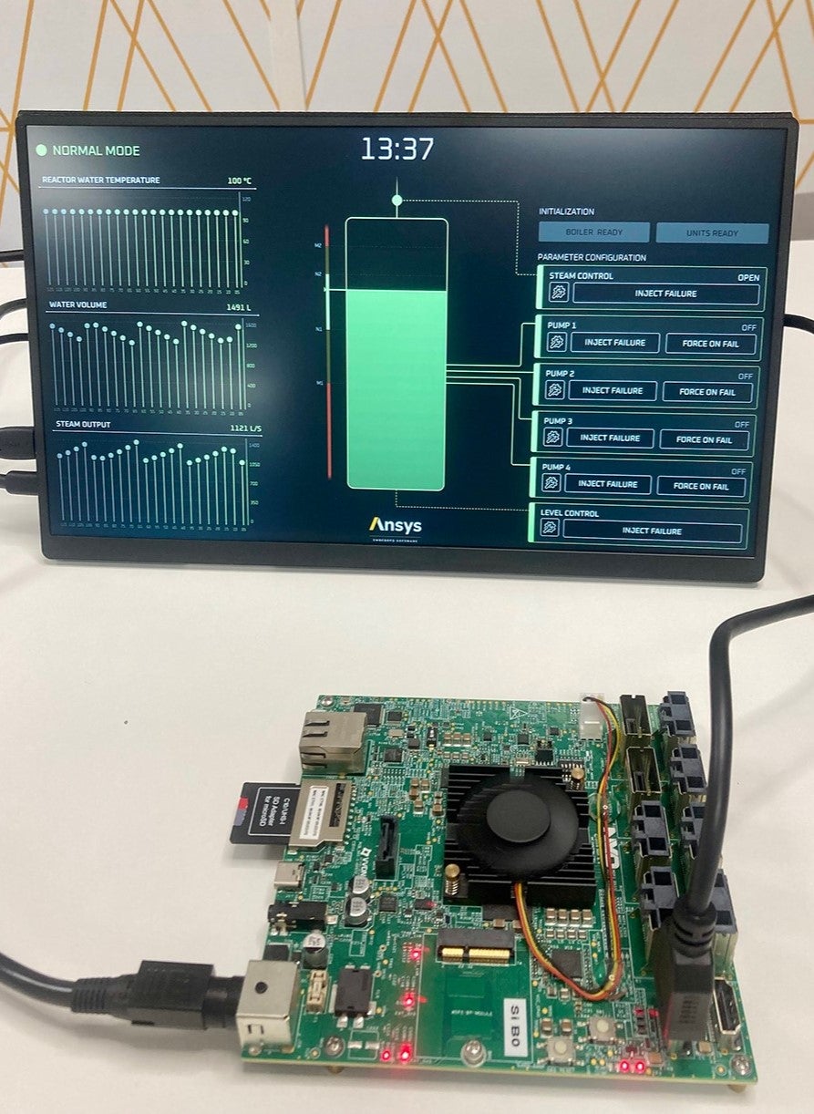
We place this file in a predefined folder of our Linux distribution and copy everything onto an SD card. We insert the SD card into our i.MX 8 board, boot it up, and…

Our Smart Boiler model in action on an i.MX 8 boardThere we have it! Our embedded HMI is running on its hardware target. Note that, despite our best efforts, we were not able to procure a nuclear reactor steam boiler for a photo-op in our offices. The pictured configuration therefore relies on the software plant model, running on the i.MX 8 board as part of the SCADE program.
Thank you for reading
In this blog, we looked at the integration of the logic for an embedded HMI, developed in SCADE Display and SCADE Suite. This concludes our Smart Boiler blog series.
If you have a SCADE installation and if you’d like to play with the Smart Boiler model yourself, you may find it here on the Ansys GitHub.
If you’d like to learn more about Ansys Embedded Display solutions, we’d love to hear from you! Get in touch on our SCADE Display product page.
About the authors
Ludovic Oddos (LinkedIn) is a Lead Product Specialist at Ansys. He has been supporting SCADE field engagements, in many industries, for more than 15 years. He has deep expertise in embedded software and its integration into various target environments.
François Couadau (LinkedIn) is a Senior Product Manager at Ansys. He works on embedded HMI software aspects in the SCADE and Scade One products. His past experience includes distributed systems and telecommunications.
-


Introducing Ansys Electronics Desktop on Ansys Cloud
The Watch & Learn video article provides an overview of cloud computing from Electronics Desktop and details the product licenses and subscriptions to ANSYS Cloud Service that are...

How to Create a Reflector for a Center High-Mounted Stop Lamp (CHMSL)
This video article demonstrates how to create a reflector for a center high-mounted stop lamp. Optical Part design in Ansys SPEOS enables the design and validation of multiple...

Introducing the GEKO Turbulence Model in Ansys Fluent
The GEKO (GEneralized K-Omega) turbulence model offers a flexible, robust, general-purpose approach to RANS turbulence modeling. Introducing 2 videos: Part 1 provides background information on the model and a...

Postprocessing on Ansys EnSight
This video demonstrates exporting data from Fluent in EnSight Case Gold format, and it reviews the basic postprocessing capabilities of EnSight.

- An introduction to DO-178C
- Scade One – Bridging the Gap between Model-Based Design and Traditional Programming
- ARINC 661: the standard behind modern cockpit display systems
- Scade One – An Open Model-Based Ecosystem, Ready for MBSE
- Scade One – A Visual Coding Experience
- Using the SCADE Python APIs from your favorite IDE
- How to integrate multiple SCADE models into one executable
- How to Verify a Model on Host with SCADE Test? (Part 4 of 6)
- Scade One – Democratizing model-based development
- Introduction to the SCADE Environment (Part 1 of 5)

© 2026 Copyright ANSYS, Inc. All rights reserved.


