-
-
April 29, 2024 at 7:48 am
 SolutionParticipant
This article is part of an embedded Human Machine Interface (HMI) design blog series. It details the process of designing a next generation embedded HMI for the control of an industrial steam boiler and implementing it with Ansys SCADE. You can find links to each part below:
- Part 1 – Designing a next-gen embedded HMI
- Part 2 – Implementing a next-gen HMI in SCADE Display
- Part 3 – Powering a next-gen HMI with SCADE Suite
- Part 4 – Integrating a next-gen HMI onto a hardware target
Introduction
This article presents an overview of the implementation, in SCADE Display, of a next-gen embedded HMI for an industrial steam boiler.
The steam boiler is like the one you’d find in a nuclear power plant. It uses a heat source (e.g. nuclear fuel) to produce steam. It is controlled by a reactive control loop that balances sensor readings (temperature, steam pressure, water level) within acceptable parameters by using actuators (water injection valves).
The embedded HMI’s role is to provide a user-friendly and aesthetically pleasing way to display the system’s status, convey issues, and prompt operator action when required.
In our previous article, we designed the HMI in collaboration between Ansys engineers and a designer, Axel Masson. We will now use SCADE Display and SCADE Suite to implement the final product.
SCADE Display
Ansys SCADE Display is a specialized tool to produce reliable and safe embedded HMIs. Its user interface is straightforward: assemble primitives into a graphical interface, then plug inputs and outputs to underlying control logic.
The synergy between design and engineering is often considered a challenge, but translating a Figma high-fidelity design into SCADE Display is remarkably seamless. Both environments use shared concepts such as graphical trees, layers, primitives, resources.
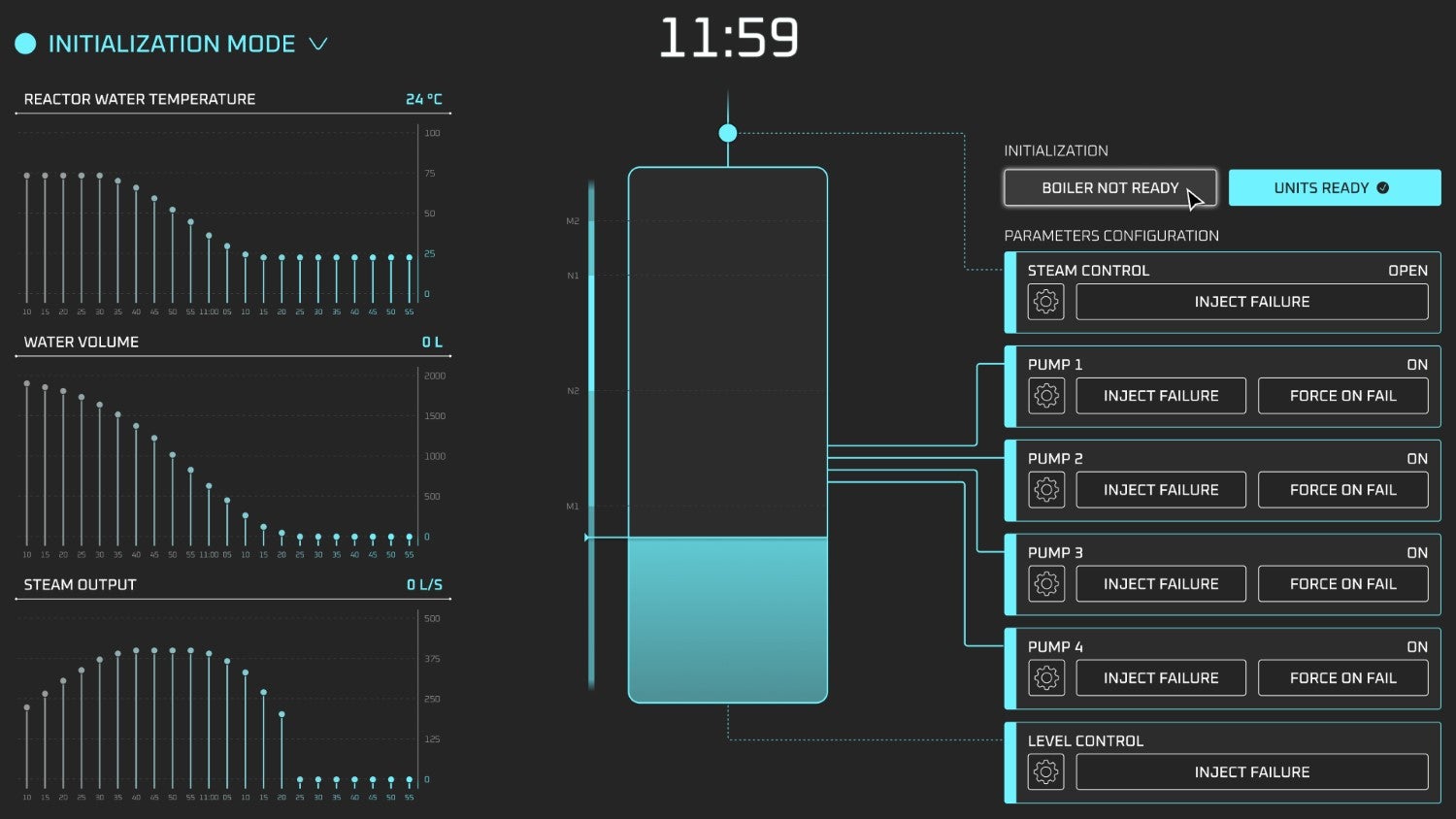
As we start our implementation, let’s have a look once again at our complete design (this time in the blue initialization mode).

Overview of our HMI panel in initialization modeReference background
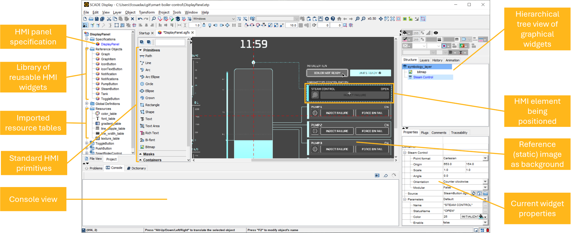
To accelerate development, the SCADE Display model is initialized with a full-size screenshot of a high-fidelity mock-up. This is a good way to visually verify that each element has the correct size, color and location, by simply positioning it against the static background image. SCADE Display’s grid alignment feature also helps “snap” the components into place.
In later stages of implementation, the background image will have served its purpose and will simply be removed.
This is what our user interface looks like during implementation:

SCADE Display user interface with static reference background and some HMI elements being positionedImporting resources
Embedded HMIs tend to run on constrained hardware, where memory may be at a premium. A first step when working with SCADE Display is to define required resources such as fonts, colors, graphical styles and images. This has the added benefit of making memory footprint predictable.
Fortunately, Figma’s “Dev Mode” makes it easy to generate graphical assets, in various file formats, from the mockups.
Furthermore, the design has been annotated to accelerate development. Fonts and graphical styles can easily be translated from requirements into a SCADE Display model.

Design elements can be easily exported from Figma and used as resources in SCADE DisplayFonts
Fonts are imported into SCADE Display through a dedicated Font Importer. This allows the translation of a TrueType font into an optimized binary font file, with only required glyphs.

The Oxanium font imported into the optimized SCADE Display font tableColors
SCADE Display uses a color table system to optimize memory usage. Each color is linked to a unique identifier that is then passed between the graphical panel and underlying logic.
In our case, the three charts at the left of the graphical panel make use of gradients to subtly highlight the most recent data points. Since each chart has 22 points, we have sampled 22 saturation variants for the main highlight colors.

Colors, including saturation variants for each highlight color, imported into a SCADE Display color tableLine styles
In the same way as colors, SCADE Display uses tables to reference line widths and stipple properties. These are easily entered from the detailed design.
Textures
Some parts of the mockup may be replicated by assembling graphical primitives such as circles or lines. Other parts, such as icons on the buttons, may be easier to implement by using images. When that is the case, Figma’s export features allow us to easily export optimized image files, with transparency. These are imported into a texture table in SCADE Display.

Icons and gradients imported from Figma into a SCADE Display texture tableCreating the embedded HMI
Reference objects
A SCADE Display model is composed of a hierarchy of containers and graphical widgets.
Repetitive parts of the HMI (such as the pump control panels on the right-hand side) can be implemented once as a Reference Object. These are small SCADE Display panels that may be instantiated multiple times in the main panel.

A pump control panel Reference ObjectIn addition to pump control panels, Reference Objects are used to implement buttons, charts, and notifications.
When appropriate, images, imported as SCADE Display textures, are used. In the panel above, the wrench icon is a transparent texture.
Assembling HMI elements
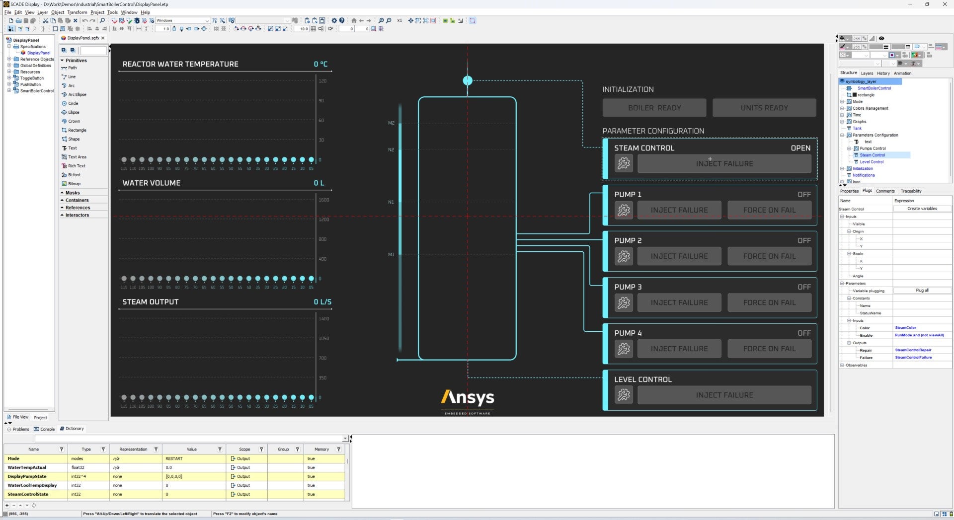
Once all elements are ready, Reference Objects and individual Display primitives are assembled and laid out on top of the static background image. Once everything is pixel-perfect, we are done with translating our mockups into a safe embedded HMI.

Overview of the complete HMI as implemented in SCADE DisplayReady for control logic integration
At this stage, our embedded HMI implementation is finalized. We are ready to plug the graphical panel into its underlying control logic.
The native integration between SCADE Display and SCADE Suite makes Suite an ideal candidate to develop this control logic using a model-based approach.
Stay tuned!
In this blog, we looked at the process of implementing an embedded HMI in SCADE Display, starting from high-fidelity mockups.
In the next blog, we will look at the underlying control logic that runs this panel, implemented in SCADE Suite and plugged to the SCADE Display graphical panel. We will conclude with the generation of a binary for the desired hardware target.
About the authors
Ludovic Oddos (LinkedIn) is a Lead Product Specialist at Ansys. He has been supporting SCADE field engagements, in many industries, for more than 15 years. He has deep expertise in embedded software and its integration into various target environments.
François Couadau (LinkedIn) is a Senior Product Manager at Ansys. He works on embedded HMI software aspects in the SCADE and Scade One products. His past experience includes distributed systems and telecommunications.
-


Introducing Ansys Electronics Desktop on Ansys Cloud
The Watch & Learn video article provides an overview of cloud computing from Electronics Desktop and details the product licenses and subscriptions to ANSYS Cloud Service that are...

How to Create a Reflector for a Center High-Mounted Stop Lamp (CHMSL)
This video article demonstrates how to create a reflector for a center high-mounted stop lamp. Optical Part design in Ansys SPEOS enables the design and validation of multiple...

Introducing the GEKO Turbulence Model in Ansys Fluent
The GEKO (GEneralized K-Omega) turbulence model offers a flexible, robust, general-purpose approach to RANS turbulence modeling. Introducing 2 videos: Part 1 provides background information on the model and a...

Postprocessing on Ansys EnSight
This video demonstrates exporting data from Fluent in EnSight Case Gold format, and it reviews the basic postprocessing capabilities of EnSight.

- Scade One – Bridging the Gap between Model-Based Design and Traditional Programming
- Scade One – An Open Model-Based Ecosystem, Ready for MBSE
- Scade One – A Visual Coding Experience
- How to Verify a Model on Host with SCADE Test? (Part 4 of 6)
- Using the SCADE Python APIs from your favorite IDE
- Introduction to the SCADE Environment (Part 1 of 5)
- ARINC 661: the standard behind modern cockpit display systems
- How to integrate multiple SCADE models into one executable
- Scade One – Democratizing model-based development
- How to Generate Code with SCADE Display (Part 6 of 6)

© 2025 Copyright ANSYS, Inc. All rights reserved.


