SCADE Model-Based Design has become a reference methodology for developing safety-critical embedded software, where reliability, verification, and traceability are essential. By enabling engineers to specify software behavior at a high level and automatically generate implementation code, it helps reduce development errors and maintain strong consistency between models and deployed software.
At the same time, Model-Based Design is not limited to highly regulated domains. Modern tools such as Scade One make the approach accessible for a wide range of embedded platforms, including lightweight microcontrollers used in less critical applications, like the Raspberry Pi Pico. Developers can design software behavior graphically and automatically generate production-quality C code and accelerating implementation.
This tutorial demonstrates how to integrate C code generated by Scade One into a simple embedded application running on the Adeept’s robot 4WD Mecanum Wheel Smart Car, based on the Raspberry Pi Pico. The example application combines two functions:
- A blinking LED using the Pico’s onboard LED
- Moving the robot’s head using a Pulse-Width Modulation-controlled servomotor. In our robot, the head is a servo-mounted ultrasonic sensor, that can be used to scan the environment.
While these two functions are simple and don’t leverage all capabilities of the robot, they allow us to demonstrate key concepts while keeping a reasonable article length.
This tutorial article walks through the hardware setup, PWM configuration, and set-up of the Visual Studio Code environment to compile and build the integrated code.
Hardware setup overview
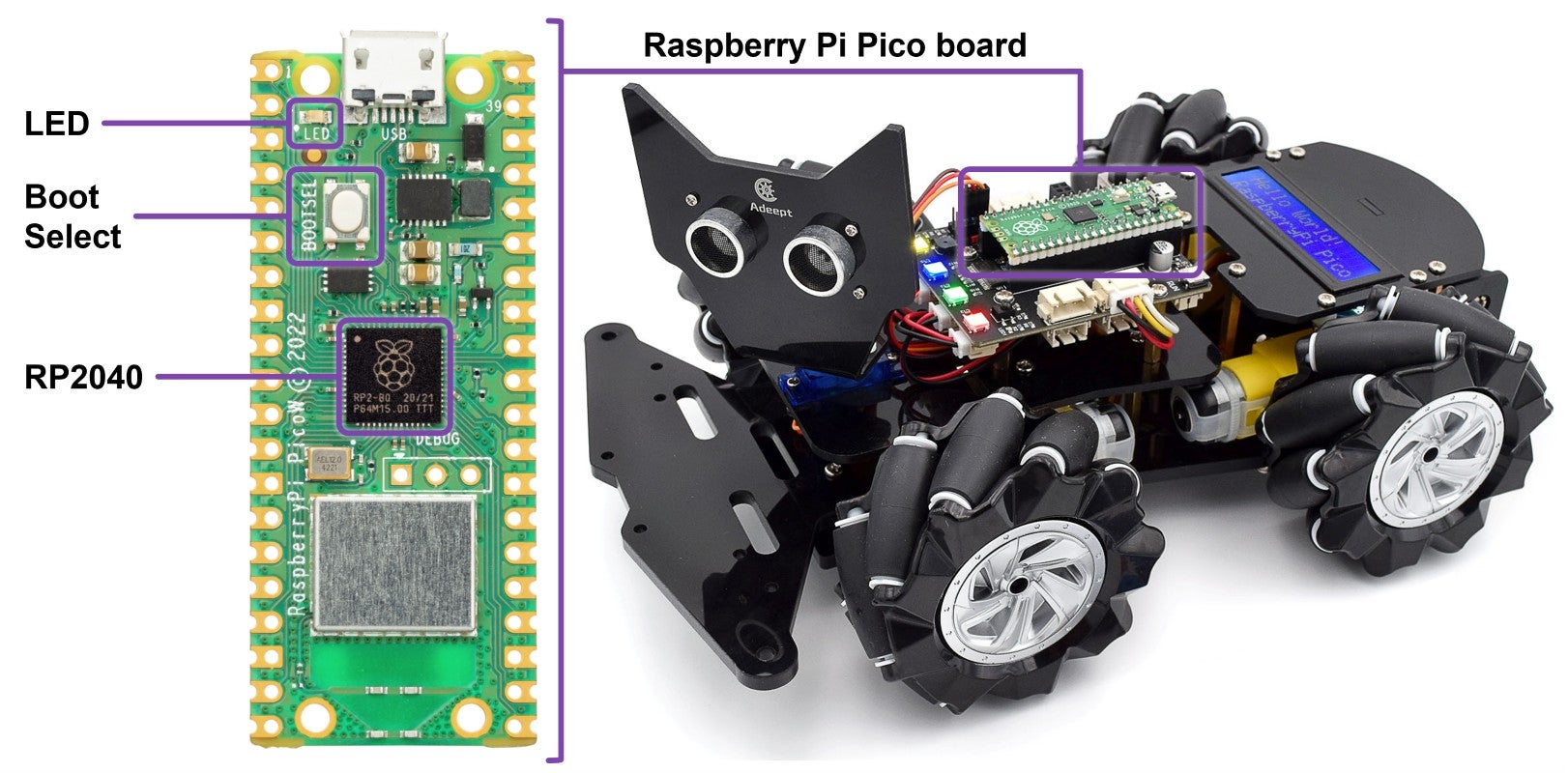
What is the Raspberry Pi Pico?
The Raspberry Pi Pico is a low-cost microcontroller board designed for embedded systems development and education. It is based on the RP2040 microcontroller, which features:
- Dual-core ARM Cortex-M0+ processors
- Up to 133 MHz clock frequency
- 264 KB SRAM
- Flexible peripherals including GPIO, PWM, SPI, I2C, UART, and timers
The Pico is widely used in robotics, control systems, and educational projects because it offers a powerful microcontroller with a simple development workflow. The official SDK allows developers to program the device in C or C++, and firmware is typically flashed using a .uf2 file copied directly to the device via USB.
For embedded control applications such as robotics, two features are particularly important:
- GPIO (General Purpose Input/Output) for digital control signals
- PWM (Pulse Width Modulation) for driving devices such as motors and servos
Why use Scade One?
Scade One is a model-based engineering and code generation environment used for developing embedded software.
Instead of writing control algorithms directly in C, engineers design the software using graphical models. These models represent software behavior, signal flows, and operation modes.
Once the software is validated through on-host model execution, debugging and analysis, Scade One can automatically generate C code suitable for embedded deployment.
Key Scade One Characteristics:
- Graphical and textual modeling language
- Deterministic execution semantics
- Automatic generation of structured-safe C code
Scade-based approach is widely used in industries such as aerospace, automotive, and industrial control.
In recent years, SCADE has also been increasingly adopted in universities to teach embedded software and Model-Based Design. The tool helps students understand how high-level software models can be transformed into executable software.
What is Model-Based Design?
Model-Based Design (MBD) is a development methodology where the software model is the central artifact in the design process.
Instead of implementing algorithms directly in source code, developers first create a formal model describing the software behavior.
A typical Model-Based Design workflow includes:
- Software modeling
- Simulation and verification
- Automatic code generation
- Code integration on target
Benefits include:
- Improved traceability between requirements and implementation
- Faster development cycles
- Early verification through simulation
- Reduced implementation errors
Scade One MBD makes it possible to maintain a consistent workflow from software modeling to deployed code, all with a high level of confidence given the level of qualification of the tool.
Application Overview
The demonstration application combines two simple embedded functions: Led blinking and Servo control.
In the Adeept Robot, the LED is connected to the Pico’s GPIO 25, while the servo controlling the robot head is connected to GPIO 7.
The servo receives a PWM signal, where the pulse width determines the servo position.
How PWM Controls a Servo
The servomotors in the robot operate using a 50 Hz PWM signal, which corresponds to a 20 ms period. Within each 20 ms period, the high-pulse duration (width) determines the servo angle.
Control values are:

Pulse Width Modulation values and resulting servo angles
The PWM configuration in this project is designed so that “PWM counts” directly represent microseconds, making it straightforward to send values produced by the Scade One model. The next section describes how to achieve that.
PWM Architecture in the RP2040
The RP2040 microcontroller implements PWM using independent PWM slices.
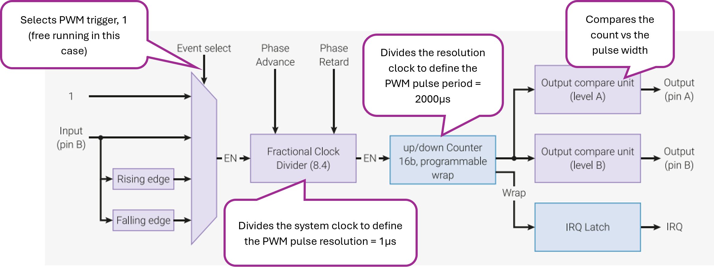
To generate a 50 Hz signal:
- The system clock (125 MHz) is divided
- A counter increments at the resulting clock rate
- When the counter reaches the wrap value, it resets
In this project:
- Clock divider = 125
- Effective PWM tick = 1 MHz (1 µs resolution)
- Wrap value = 19999
This produces: 1 MHz / 20000 counts = 50 Hz
Because each PWM tick represents 1 µs, the PWM duty cycle can be set directly using microsecond values. In this way:
- The hardware generates the PWM signal automatically every 20 ms, with width resolution of 1 µs
- The application code can update the duty cycle at any time (e.g., every control loop iteration), that is, comand the position of the head by providing a pulse width.
Scade One Model
The model implements two simple behaviors: LED blinking and servo motion.
When designing software with Scade One, interaction with external software components is supported (e.g. PICO SDK functions), but these components must remain outside the (application) model in a way that preserves simulation capability. Simulation requires generating, compiling, and executing code on the host platform. Consequently, any external components must be compatible with the host (PC) architecture, which is not true for the SDK components that are meant for the PICO architecture.

The behavior is described using two independent state machines, running in parallel.
Interface
The LED blinks at a frequency set by the LED_delay input, while the robot head moves from left to right at a frequency set by the SERV_delay input.
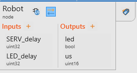
The model provides two outputs:
led: a Boolean signal that controls the LED state (true = ON, false = OFF)us: a pulse width value (in microseconds) used to generate the PWM signal, which defines the position of the robot head. This value range is between 1000 and 2000 us, corresponding to an angle range of [-90 .. 90]°.
LED control
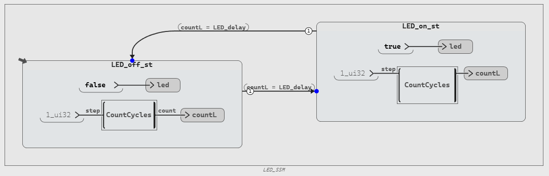
The LED_SSM state-machine with two states (LED_off_st and LED_on_st) toggles the led output between false and true. In each state, a CountCycles counter increments every cycle. When countL = LED_delay, the machine transitions to the other state, producing a periodic LED blink.
Head control
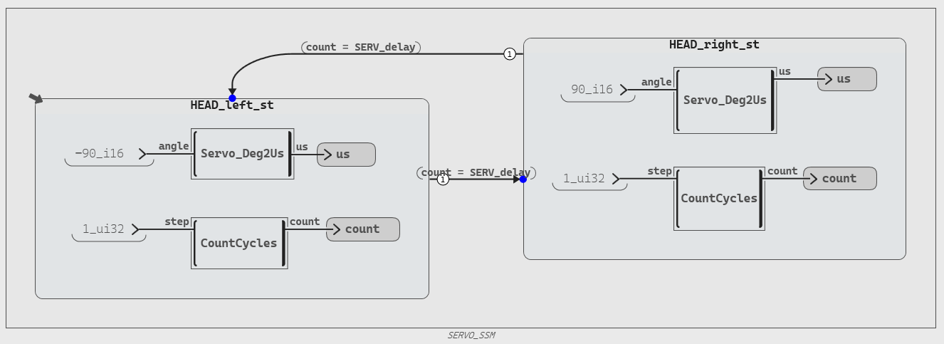
The SERVO_SSM state machine with two states (HEAD_left_st and HEAD_right_st) alternates the servo angle between −90° and +90°. In each state, Servo_Deg2Us converts the fixed angle to a PWM value (us), while a CountCycles counter increments; when count = SERV_delay, the machine transitions to the other state, producing periodic left-right motion.
Simulation
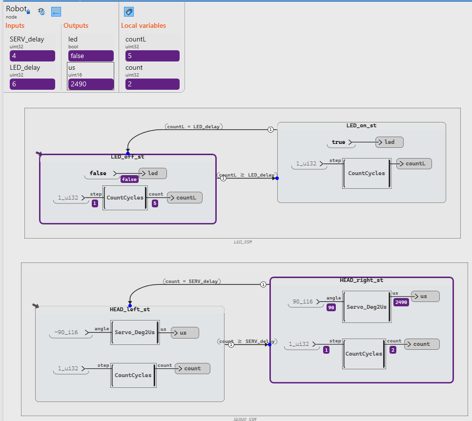
Live debug of the Robot operator in Scade One. Active state machine states are highlighted.
Before deployment, it is better to analyze the behavior of the model. To do this, we launch our model in debug mode on a host laptop.
The simulation was launched and executed several steps; at this point the LED is OFF and waiting for its counter to reach 6 before switching ON. The servo is positioned to the right (+90°) and is waiting for its counter to reach 4 before switching to the left position.
Code generation and integration
We are now ready to integrate our model onto the embedded target. When launching code generation from Scade One, the code generator produces the files below. For details on how to generate the code, see Scade One Student Quick Getting Started:
- Robot_blinker.c: implementation of the SCADE model logic
- Robot_blinker.h: public interface of the model
- swan_consts.c: definitions of global constants used by the generated code
- swan_consts.h: declarations of those constants.
- swan_sensors.h: interface for external inputs
- swan_types.c: implementation of custom data types (if required by the model)
- swan_types.h: definitions of all data types used by the generated code
The user should create an integration file (e.g. picoBlink.c) including the Robot_blinker.h file.
// === PICO SDK  ===
#include "pico/stdlib.h"
#include
#include
#include
#include "hardware/pwm.h"

// === SCADE API  ===
#include "Robot_blinker.h"  // in SCADE_DIR

// === Hardware pins ===
#define LED_PIN 25   // Onboard LED on Raspberry Pi Pico
#define SERVO_PIN 7   // Adeept board X11 "SIG" -> GP0
#define PIN_PWM_SLICE 3 // RP2040 slice hardcoded for pin 7
Initialization
The init_Robot function initializes the hardware and the SCADE-generated code for the robot. It first sets up standard I/Os, configures the LED pin as a digital output, and assigns the servo pin to the PWM function. It then initializes the PWM peripheral using the Pico SDK: the clock divider is set to obtain a 1 MHz PWM tick rate, and the wrap value is configured to 19,999, resulting in a 20 ms period (50 Hz), which is suitable for servo control. The PWM slice corresponding to the servo pin is started with this configuration. Finally, the function calls Robot_init_blinker to initialize the internal state and outputs of the generated SCADE model.
// === Robot init fuction ===
static inline void init_Robot(void) {
    stdio_init_all();
    gpio_init(LED_PIN);
    gpio_set_dir(LED_PIN, GPIO_OUT);
    gpio_set_function(SERVO_PIN, GPIO_FUNC_PWM);

    // 125 MHz / 125 = 1 MHz tick => wrap 19999 gives 50 Hz (20 ms period)
    pwm_config cfg = pwm_get_default_config(); // PICO SDK pwm configuration
    pwm_config_set_clkdiv(&cfg, 125.0f); // to achieve 1M PWM ticks per second
    pwm_config_set_wrap(&cfg, 19999); // a period of 20K (50hz) ticks per PWM pulse
    pwm_init(PIN_PWM_SLICE, &cfg, true); // the RP2040 slice is hardcoded for pin 7

    // init the memories and outputs of the SCADE-generated code
    Robot_init_blinker(&outC);
}
Main function
The main function calls the initialization function and continuously executes the control loop driven by the SCADE-generated code.
After calling init_Robot() and waiting briefly for stabilization, it enters an infinite loop where the Robot_blinker function is invoked with fixed delay parameters to compute the current outputs. These outputs are then applied to the hardware: the LED state (outC.led) is set using a GPIO write, and the servo position is controlled by updating the PWM pulse width (outC.us). The loop runs periodically with a 100 ms delay (≈10 Hz), defining the execution rate of the model.
int main(void) {

    init_Robot();

    while (true) {
        // --- Call SCADE-generated logic ---
        Robot_blinker(SERVO_FREQ, LED_FREQ, &outC);

        // --- Drive the pin with SCADE output ---
        gpio_put(LED_PIN, outC.led);
        pwm_set_gpio_level(SERVO_PIN, outC.us);

        // Model tick period (adjust to your design’s sampling time)
        sleep_ms(100); // main loop at ~100 Hz; tweak as needed
    }
}
Compile and Build using Visual Studio Code and PICO SDK
The build is demonstrated using Visual Studio Code together with the Pico C SDK.
Prerequisites
Before creating a Pico Project, first Install:
- Visual Studio Code
- Raspberry Pi Pico C SDK
- Raspberry Pi Pico VS Code extension
- Microsoft CMake Tools extension
Step 1: Create a New Pico Project
- Open Visual Studio Code
- Press Ctrl+Shift+P
- Select:
Raspberry Pi Pico: New Pico Project
C:\PicoProjects\line_follower
- Select C as the language.
The extension creates a project containing:
- main.c
- CMakeLists.txt
- . vscode configuration files
Press Ctrl+Shift+P and run:
Raspberry Pi Pico: Configure CMake
The terminal should show a successful configuration and select Ninja as the generator.
Step 3: Build the Project
Run:
Raspberry Pi Pico: Compile Pico Project
The build produces a .uf2 firmware file inside the build directory.
Step 4: Flash the Pico
- Hold BOOTSEL on the Pico.
- Connect the Pico to the computer via USB.
- Release the button.
The device appears as a USB storage drive.
Then run:
Raspberry Pi Pico: Flash Pico Project (USB)
The .uf2 file is copied to the Pico and the program starts automatically.
And there you have it! Our robot is happily blinking its light and moving its head from side to side:
Conclusion
This tutorial demonstrated how Model-Based Design using Scade One can be combined with the Raspberry Pi Pico to implement a simple embedded robotics application.
By generating C code from a Scade One model and integrating it into a Pico project, developers can bridge the gap between high-level software models and real hardware execution.
Even a simple example such as a blinking LED and a servo-driven robot head illustrates the core workflow:
- Model software behavior in Scade One
- Generate deterministic embedded C code
- Integrate the generated code with hardware drivers
- Deploy the application to an embedded target
This workflow highlights the practical benefits of Model-Based Design: faster design, improved reliability, and a clear connection between software design models and the embedded code. You can use Scade One for your academic projects! Get it from Ansys SCADE Student Free Software Download | Ansys.
About the author
|

|
Dr. Jair Gonzalez (LinkedIn) has extensive experience in Model-Based Development (MBD) for embedded systems, spanning teaching, research, and business leadership. Currently serves as Sr. Principal Engineer at Ansys, where he promotes the adoption of SCADE MBD approach across diverse industries, including Railway, Energy, Robotics.
|