Tagged: aim tutorial, discovery-aim, electromagnetics, fluids
-
-
September 26, 2022 at 10:00 am
 SolutionParticipant
This example is taken from Cornell University’s ANSYS AIM Learning Modules
Problem Specification
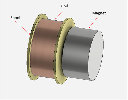
This problem is intended to address the questions of force calculations as well as modeling of permanent magnets in asymmetric and three dimensional geometries.The spool is made out of brass, the coil is made out of copper and the magnet is made of NdFe30 (Neodymium Iron). In this demonstration, two cases will be considered and the force between the magnet and the coil will be determined.
f = f(i,R,s)
where
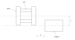
f = force between magnet and coil i = current, R = horizontal displacement s = vertical displacement
In case one, both s = 0 and R = 0.254mm are held constant. Therefore, f = f(i)
In case two, s = 0mm and i = 50mA are kept constant. Therefore f = f(R)

In the first case, the current will vary from from 0-100mA in 10mA intervals. In case two, the axial displacement will vary from 0.0-.5mm in 0.05mm intervals.
Pre-Analysis
Governing Equation
Magnetostatics is the study of magnetic fields in devices where the magnetic field is generated from DC (steady) currents and/or permanent magnets. Magnetostatics is a special case of Maxwell’s equations, which form the basis of electromagnetism.
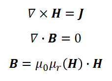
For magnetostatics the electric field inside of a current carrying coil is completely decoupled from the magnetic field, and the following Maxwell’s equations are solved for magnetostatics –

Where ∇ denotes divergence, H is the magnetic field intensity, J is the current density, and B is the magnetic flux density.
Geometry
In this video, you will learn how to import the geometry and how to define a parameter for the distance between the magnet and spool.
Physics Setup
In this video, you will learn how to:
- Assign material properties
- Define boundary conditions and parameterize current
- Define output parameter for force magnitude
- Define design points
Design Point Study
Case 1: The current will vary from 0-100mA in 10mA intervals
As shown in the above video, all the 10 DEsign Points are updated. The force results will look as shown in below image.

Case 2: The axial displacement will vary from 0.0-.5mm in 0.05mm intervals. In the design parameters dashboard, change all the current data points to 50mA. Then iterate the horizontal data points from 0.05mm-.5mm by 0.05mm. Click update all to see results. The results will look like shown below.
Results Evaluation
The following video shows how to compute Magnetic Flux Density
-


Introducing Ansys Electronics Desktop on Ansys Cloud
The Watch & Learn video article provides an overview of cloud computing from Electronics Desktop and details the product licenses and subscriptions to ANSYS Cloud Service that are...

How to Create a Reflector for a Center High-Mounted Stop Lamp (CHMSL)
This video article demonstrates how to create a reflector for a center high-mounted stop lamp. Optical Part design in Ansys SPEOS enables the design and validation of multiple...

Introducing the GEKO Turbulence Model in Ansys Fluent
The GEKO (GEneralized K-Omega) turbulence model offers a flexible, robust, general-purpose approach to RANS turbulence modeling. Introducing 2 videos: Part 1 provides background information on the model and a...

Postprocessing on Ansys EnSight
This video demonstrates exporting data from Fluent in EnSight Case Gold format, and it reviews the basic postprocessing capabilities of EnSight.

- Discovery Live: How to change units
- Discovery AIM tutorial – 3D Finite-Element Analysis of a Bike Crank
- Discovery AIM tutorial – Analysis of cantilever beam with I cross-section
- Discovery SpaceClaim: Getting Started Tutorials
- Discovery AIM – Scaling deformation contour results
- FAQ: Missing Areas of the User Interface in Discovery Live
- Convert 2D Drawings to 3D Models in Minutes with SpaceClaim
- Creating a Helical Geometry in SpaceClaim
- Discovery AIM tutorial – Structural Analysis of Plate with Hole
- Project Text to 3D Geometry in SpaceClaim

© 2025 Copyright ANSYS, Inc. All rights reserved.


