Ansys Assistant will be unavailable on the Learning Forum starting January 30. An upgraded version is coming soon. We apologize for any inconvenience and appreciate your patience. Stay tuned for updates.
A cube shaped cavity filled with water, shown below, is subjected to a moving lid at a constant velocity which creates rotating recirculation areas in the fluid contained by the cavity.
Plot the velocity vectors, velocity and pressure contours of the cavity as it is subjected to a driving force by the lid.
Pre-Analysis
Governing Equation
The following nondimensional equations govern conservation of mass and momentum.
These equations can be combined in order to create a governing equation that will dictate the flow in our lid-driven box. Below is the equation which was created when combining the above.
The terms on the left govern the net convection flow in the volume while the terms on the right govern net diffusion, with the exception of S which represents source generation of the flow.
Reynold’s Number
Using the equation below, the Reynolds number can be calculated for the problem. This will allow us to predict how the flow will behave inside the box before running the simulation. It is specified in the problem that the inside length of the box is 0.1 m and the speed of the lid is 1 m/s. Since the fluid inside of the box is water, the density is 997.05 kg/m^3 and the viscosity is 0.00089002 N*s/m^2. These values can be found online or later on in the Material properties section of the Physics template.
The resulting value from the Reynolds number calculation indicates that the flow will be turbulent and will produce multiple eddies.
Geometry
There are two ways of creating the flow volume which will be tested. The first is to make a cube and the second is to make a hollow box and extract the volume. The first option would be very straight forward, but the second is more realistic in the physical world. This tutorial will explore the latter option.
In this video, you will learn how to specify Boundary layers and generate a tetrahedral mesh.
Physics Setup
In this video, you will learn how to specify a moving wall and symmetry boundary conditions.
Results Evaluation
In this video, you will learn how to view velocity vectors and total pressure within the flow volume.
Validation
One way to verify the AIM solution is to compare it with results from Fluent. Below is the velocity contour of a lid driven cavity done in Fluent in a study called “Three Dimensional Lid Driven Cavity” by Ashok Sivanandham, Boris Makarov and Laith Zori.
Below is the velocity contour created by Discovery AIM.
By comparing it to the velocity contours, we can see that they are similar. There is an area of high velocity at the top of the box where the wall is moving and a medium velocity at the right wall. Also, there is a spread of low velocity that sweeps the bottom left corner and goes up while there is an area of very low velocity in the center.
Featured Articles
Introducing Ansys Electronics Desktop on Ansys Cloud
The Watch & Learn video article provides an overview of cloud computing from Electronics Desktop and details the product licenses and subscriptions to ANSYS Cloud Service that are...
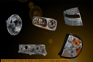
How to Create a Reflector for a Center High-Mounted Stop Lamp (CHMSL)
This video article demonstrates how to create a reflector for a center high-mounted stop lamp. Optical Part design in Ansys SPEOS enables the design and validation of multiple...
Introducing the GEKO Turbulence Model in Ansys Fluent
The GEKO (GEneralized K-Omega) turbulence model offers a flexible, robust, general-purpose approach to RANS turbulence modeling. Introducing 2 videos: Part 1 provides background information on the model and a...
Postprocessing on Ansys EnSight
This video demonstrates exporting data from Fluent in EnSight Case Gold format, and it reviews the basic postprocessing capabilities of EnSight.