This blog is part of a series on formal verification of applications developed with SCADE Suite. If you are new to formal verification or want an overview of the SCADE Suite Design Verifier tool, we recommend starting with this blog: Introduction to formal verification and SCADE Suite Design Verifier.
In this article, we will show you how SCADE Suite Design Verifier can be used in the early design stages to ensure that your software applications are free of common runtime errors that may be hidden in your software design.
Introduction
Runtime errors are a class of software defect that are triggered by invalid arithmetic operations resulting in, among other things, division-by-zero, data type overflows, float infinity and not a number (NaN). These defects typically occur during software program execution and can lead to erroneous execution of the program.
For software systems where a high level of dependability is required, runtime errors must be detected and fixed in the early design stage of the application to prevent any unexpected behavior at runtime.
Formal verification techniques such as static analysis and model checking can be used to detect runtime errors in a software design or program. These techniques are integrated into several industrial tools and commonly used to verify large-scale software systems. In this blog, we will focus on the runtime error detection feature of SCADE Suite Design Verifier — a model checker for software applications developed in the Scade language. We will introduce the predefined checks available in the tool and illustrate how it can be used to verify the absence of runtime errors in software specifications.
Runtime Error Checks in SCADE Suite Design Verifier
SCADE Suite Design verifier (SCADE DV) defines a number of predefined checks, also known as predefined proof objectives, to prove the absence of integer and floating-point errors resulting from invalid arithmetic operations. These proof objectives (PO) include:
- Integer division-by-zero: ensures that the denominator of each integer division is non-zero.
- Integer Overflow: guarantees that all integer expressions fit within the range of their data types. It also ensures that a model does not contain any invalid cast operations from floating-point data types to integer data types.
- Float Infinity: ensures that all floating-point expressions are never evaluated to infinity ($-\infty$ or $+\infty$), which implicitly verifies that floating-point expressions do not overflow and divide by zero.
- Float Not-a-Number: when valid, guarantees that all floating-point expressions in your design never evaluate to Not-a-Number (NaN).
Table 1 summarizes the mapping of checks performed by SCADE DV to detect standard arithmetic errors.

Table 1. Mapping table of SCADE DV arithmetic checks on standard arithmetic errors.
¹ SCADE DV raises an Integer overflow error if there is an invalid cast operation from floating-point types to integer types.
Runtime Error Verification workflow
Now, let us illustrate the runtime error verification workflow with SCADE DV. For this purpose, let us consider the SCADE project RTE.etp. This project consists of a simple operator, RTE_operator, depicted in Figure 1. In this operator, the input and output interfaces are single-precision floating-point variables (float32) and the output is equal to the following expression: $(a+b) ÷ c$ .

Figure 1. Diagram of RTE_operator, outputting $(a+b) ÷ c$
To run a runtime error analysis, you would follow the steps described by Figure 2.

Figure 2: Runtime error verification workflow with SCADE Suite Design Verifier
Step 1: Enable SCADE DV
To enable SCADE DV, you may either create a verification project, which uses the design project RTE.etp as a library or directly enable SCADE DV in the design project and create a package for the verification modules.
If you choose to create a verification project, then you should follow the steps illustrated by Figure 3:
- Go to the File tab and click New (or press Ctrl+N).
- From the New panel, go to the Projects tab and select SCADE Suite project for Design Verifier.
- Fill in the name and the location path of your project and click OK. Note that during the creation of your project, you can choose to link the project to an existing workspace or automatically generate a new one.
- In the newly created project, select your design project and insert it as a library.
To summarize, we created the verification project RTE_DV.etp to verify the absence of runtime errors in operator RTE_operator, defined in library RTE.etp.
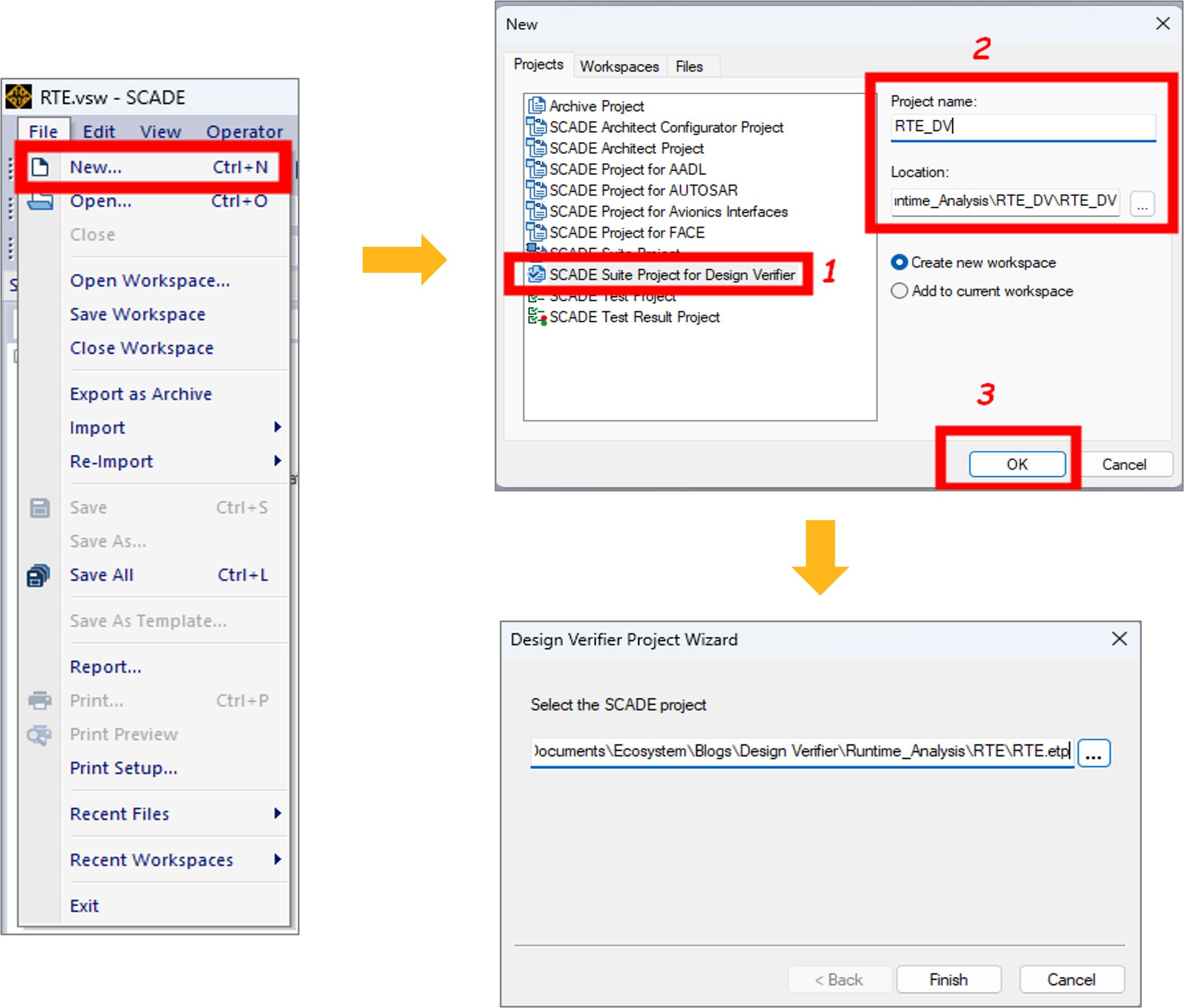
Figure 3: Creating a SCADE Suite project for Design Verifier
Once you create a verification project, SCADE DV is enabled, and you get the different views shown by Figure 4:
- In FileView, an internal file (RTE_DV.I4) and a new Scade library (libverif.etp) are automatically added to the project. The internal file enables the functionalities of SCADE DV while the library is composed of a set of operators that are used to express the verification properties.
- In the Scade view, you can display the contents of the newly-created project and the content of referenced libraries.
- The Design Verifier view displays proof objectives and verification strategies that are considered to verify the correctness of the
RTE_operator specification. In the second step of the verification workflow, we will see how proof objectives and verification strategies are added.
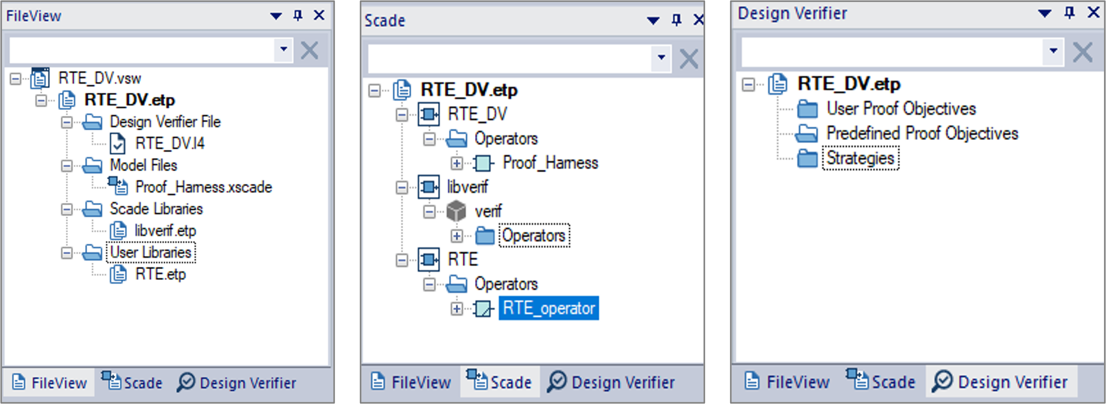
Figure 4: Different views after the activation of SCADE Design Verifier
In case you choose to enable SCADE DV directly in your design project, you should follow the steps illustrated in Figure 5:
- In the FileView or Scade view panel, select the active SCADE project.
- From the Project menu, click Enable Design Verifier.
- In the popup window, click OK and verify that filename.I4 is created.
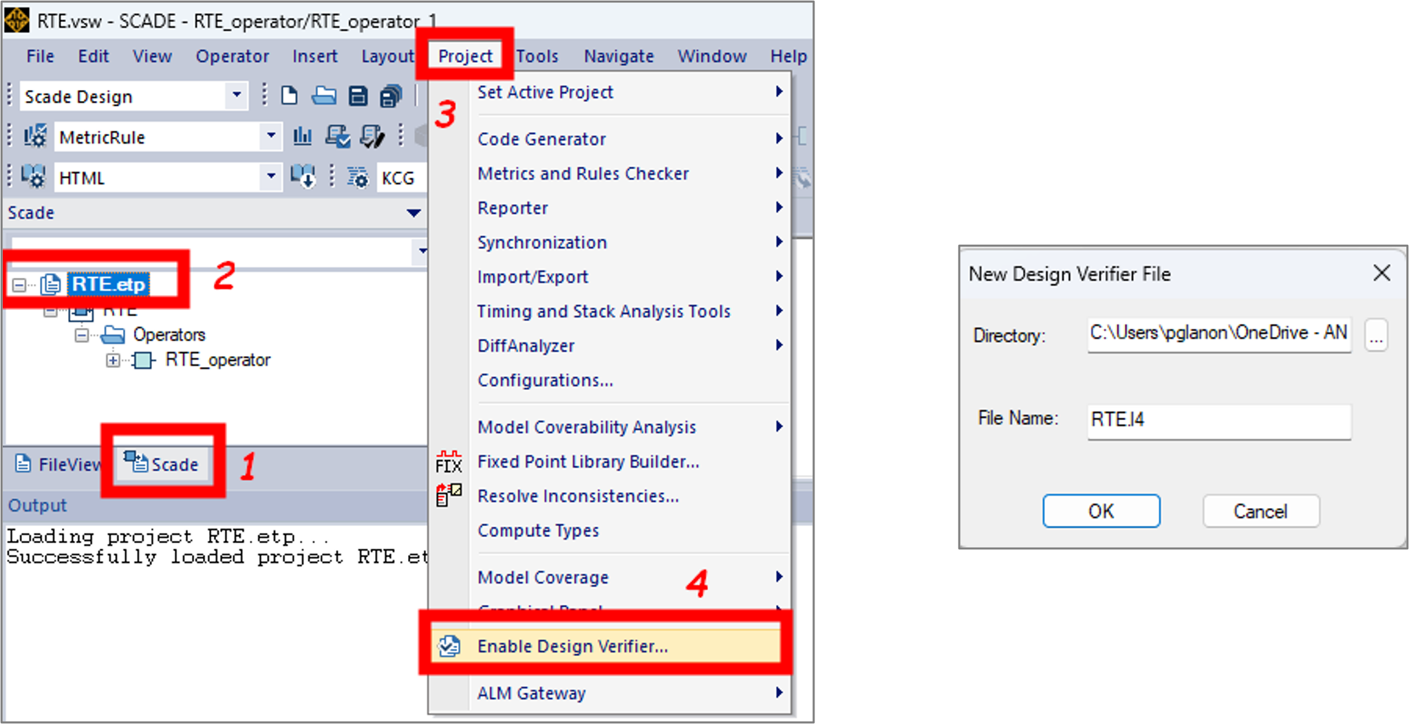
Figure 5: Enabling SCADE DV in your design project
Note: When you enable SCADE DV in your design project, the built-in library libverif is not added automatically to your project. You need to insert it manually from your SCADE installation folder.
Step 2: Specify the proof objectives
Once SCADE DV is enabled, you can now specify the predefined proof objectives (PO), i.e. the runtime errors that will be verified by the model checker. A predefined PO can directly be inserted from the library of components under verification, or you can create a proof harness — i.e, a Scade operator defined in your verification project which references the library’s components under verification — and insert a predefined PO from the proof harness. The creation of a proof harness can be beneficial when you need to constrain the model interfaces in the verification stage without changing your design.
In our case, we will insert a predefined PO that checks the absence of float infinities and Not-a-Number on RTE_operator, our library component under verification. For this purpose, let us follow the steps below:
- From the Scade view, go to the
RTE library, right-click RTE_operator and insert a predefined PO as described by Figure 6. Explore the Design Verifier view to check the new predefined PO.
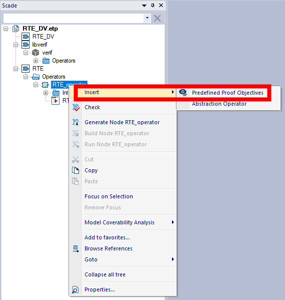
Figure 6: Inserting a predefined PO into your design project
- From the Design Verifier view, rename the inserted predefined PO. From its Properties view, select float Infinity and Not a Number as shown in Figure 7.
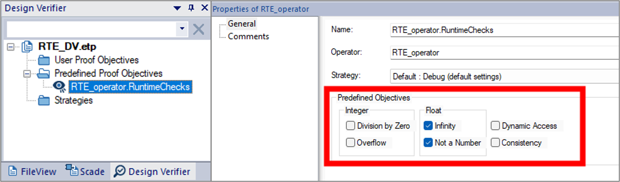
Figure 7: Selecting predefined POs
Step 3: Specify the verification strategies
To analyze the inserted predefined PO, you must associate it with a verification strategy. In SCADE DV, you can either select a set of default and configurable strategies, or you can specify a custom strategy based on Prover PSL Strategy definition syntax. We will dive into these strategies in a future post. For now, let us associate our predefined PO with the default debug strategy, as shown in Figure 8. This strategy tries to prove a property using a bounded model-checking technique.
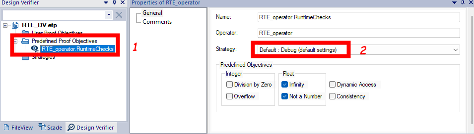
Figure 8: Applying a Strategy to a PO
Step 4: Launch the analysis
To run a formal analysis, right-click the predefined PO and click Analyze as shown in Figure 9.
Once you launch the analysis, a window pops up with a progress bar that shows the status of the verification tasks. From this window you may click Abort to interrupt the analysis at any time. When the analysis is completed, a Done message appears under the progress bar and you can close the analysis window.
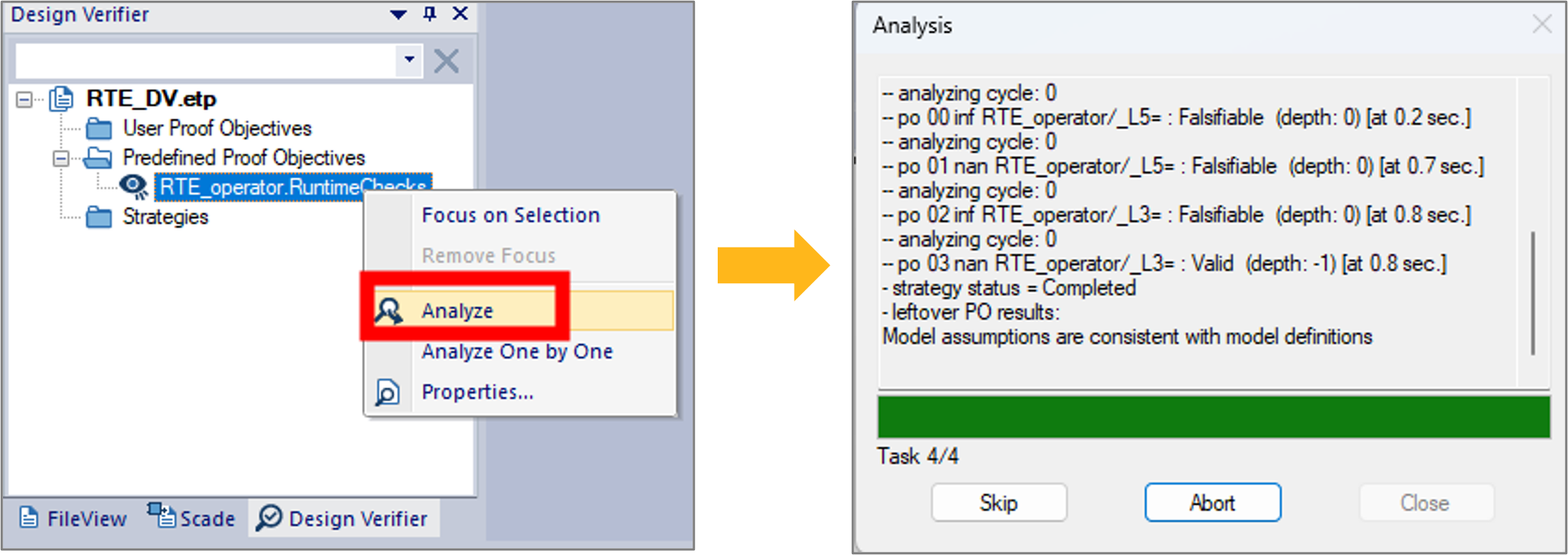
Figure 9: Launching the verification analysis
Step 5: Review the results
Once the analysis is completed, results are displayed in the output browser as shown by Figure 10 where the Falsifiable keyword means that the verified PO can be false. In our example, this indicates that some floating-point operations in RTE_operator can lead to infinity and NaN.
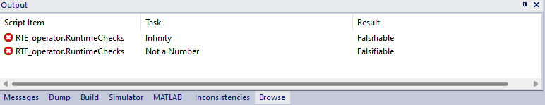
Figure 10: Viewing analysis results
An analysis report is also generated, which provides details on the tasks (i.e. the checks) performed by the model checker and their verification strategies. Figure 11 illustrates the report generated for our application example. For each falsifiable task, the checker generates one or multiple counter-examples, that lead to the scenarios in which the verification is false. These counter-examples can be loaded in the SCADE Simulator to pinpoint the error and fix the design accordingly.
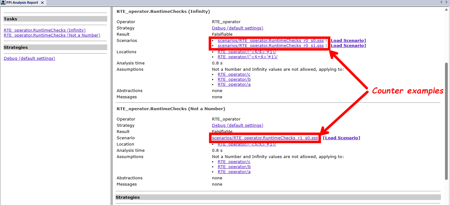
Figure 11: Generated analysis report for our application example
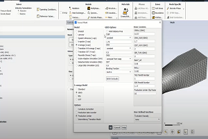
Before loading the counter-examples, you first need to configure the SCADE Simulator. Figure 12 shows the configuration steps for the simulator:
- Open the configuration settings (steps 1-3).
- Select the code generator (steps 4 & 5).
- Select the SCADE Simulator as an execution target (steps 6 & 7).
- Enable the SCADE Debugger and validate the changes (steps 8-10).
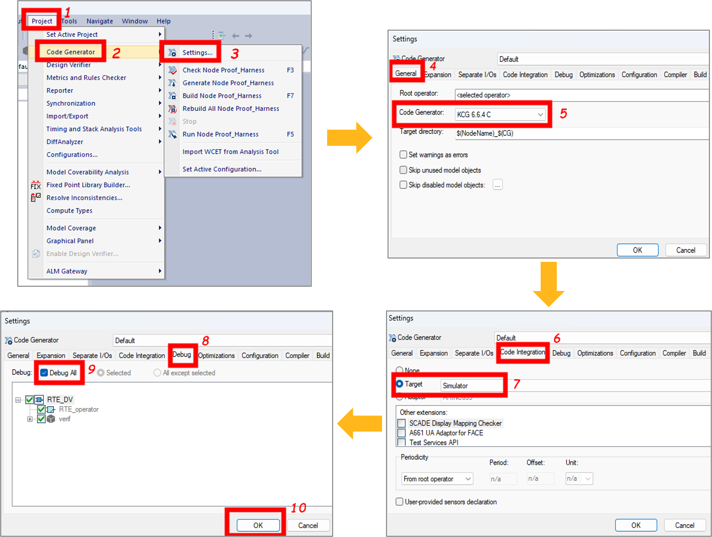
Figure 12: Configuring the simulator to run counter-examples
Now that the SCADE Simulator is configured, you can select the operator under verification and load the counter-example scenarios generated by SCADE DV. Figure 13 illustrates how to load the counter-example scenario that led to a NaN:
- From the Scade view, select the
RTE_operator (steps 1 & 2).
- From the generated report, load the scenario (step 3).
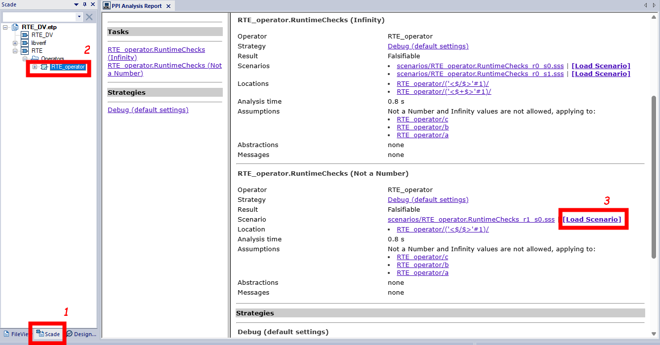
Figure 13: Loading a counter-example in SCADE Simulator for debugging
As soon as you load a scenario, the SCADE simulator is launched, and you can run the simulation to identify the computation paths that lead to a runtime error. Figure 14 shows the results of the counter-example scenario that led to a NaN. As shown by the figure, there is a quiet NaN (qNaN) in the output’s computation path when $c = 0.0$ for any pair of values $(a, b)$ .
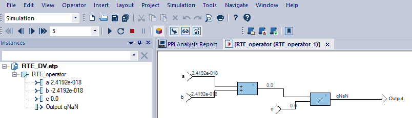
Figure 14: Counter-example debugging in the SCADE Simulator
Adding execution context to your verification using Scade assertions
To avoid considering values that are known to be unreachable in your software design, you can use assume assertions to constrain the definition domain of your software components’ input interfaces. This will add an execution context to your verification and will reduce the exploration space of SCADE DV’s model checkers.
When designing a software component, you can either insert assume assertions directly into the component’s specification model, or if you need further validation before incorporating the assertions into the specification model, you can add a proof harness referencing the component and its assumptions. Figure 15 shows a proof harness defined in verification project RTE_DV.etp. This proof harness is a function operator that references RTE_Operator, our component under verification with assumptions made on its input interfaces.
When assume constraints are expressed on the inputs of a software component, a consistency check must be made to verify that the constraints are not contradictory. For instance, if we consider an input $u$ , we cannot express a constraint that stipulates that $u$ is strictly greater than zero and at the same time less than zero. To ensure that constraints stated on input interfaces are consistent, SCADE DV provides a predefined PO that is highlighted in Figure 16. When this PO is checked, the model checker detects inconsistencies in the constraint statements, generating a counter-example if they are any. In future posts, we will cover this predefined PO in detail.

Figure 15: Using assertions in your component
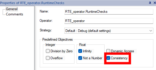
Figure 16: Enabling consistency checks
Considering the proof harness depicted in Figure 15, you can add a new predefined PO with the same objectives for runtime error detection (i.e. float infinity and NaN). If you run the verification with this newly defined PO, you will get valid results as depicted in Figure 17. This means that there are no float infinities and NaN as long as the inputs of the component under verification fit within their definition domains as specified by the assume assertions. This makes the interpretation of results more accurate and eliminates, from the model checker’s exploration space, values that are not significant for our application example.
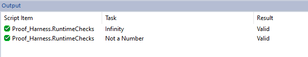
Figure 17: Verification results with constrained inputs
Conclusion
In this article, we saw how to detect runtime errors using SCADE DV. We had an overview of the predefined checks performed by the tool and illustrated the workflow to detect errors and understand how they trigger. We saw how to play error scenarios in the SCADE Suite simulator to understand and fix issues, and how to prune the checker’s exploration space with assertions.
In our next post, we will demonstrate how SCADE DV can be used for the verification of functional and safety requirements.
In the meantime, if you want to experiment, you may download this article’s example model here (or browse its sources).
If you wish to know more about how SCADE DV can improve your embedded design workflow, you may contact us from the Ansys SCADE Suite page.
About the author
|

|
Dr. Philippe Glanon (LinkedIn) is a technical expert in the design and development of Safety-Critical Embedded Systems and Software. As a senior application engineer at Ansys, he promotes model-based design solutions and he supports customers in aerospace, railways and automotive industries to achieve success through the adoption of SCADE products.
|