-
-
April 10, 2024 at 10:47 am
 SolutionParticipant
This article is part of an embedded Human Machine Interface (HMI) design blog series. It details the process of designing a next generation embedded HMI for the control of an industrial steam boiler and implementing it with Ansys SCADE. You can find links to each part below:
- Part 1 – Designing a next-gen embedded HMI
- Part 2 – Implementing a next-gen HMI in SCADE Display
- Part 3 – Powering a next-gen HMI with SCADE Suite
- Part 4 – Integrating a next-gen HMI onto a hardware target
Introduction
This article presents a collaborative effort between Ansys engineers and a designer, Axel Masson, to design a modern embedded HMI for an industrial steam boiler. We will use SCADE Display and SCADE Suite to implement the final product.
Many industrial control systems favor function over form. They are built for reliability first, run on constrained hardware and are meant to be used by trained professionals. However, in an era where most of us carry powerful touchscreen devices in our pockets, good HMI design has become an everyday expectation.
In this post, we will embark on a mission to create a Smart Boiler Control HMI with a modern look and feel. This endeavor involves a close collaboration between engineers and a professional designer, resulting in a legible, user-friendly, and visually appealing interface.
Let’s start with a sneak peek at the end result:
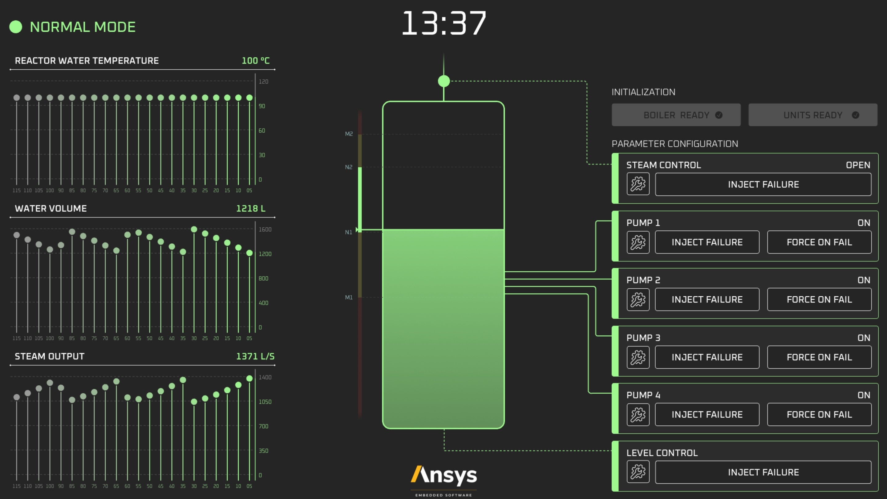
Screenshot of the final HMI, implemented in SCADE DisplayNot bad, considering many industrial control panels in the wild would look like this:
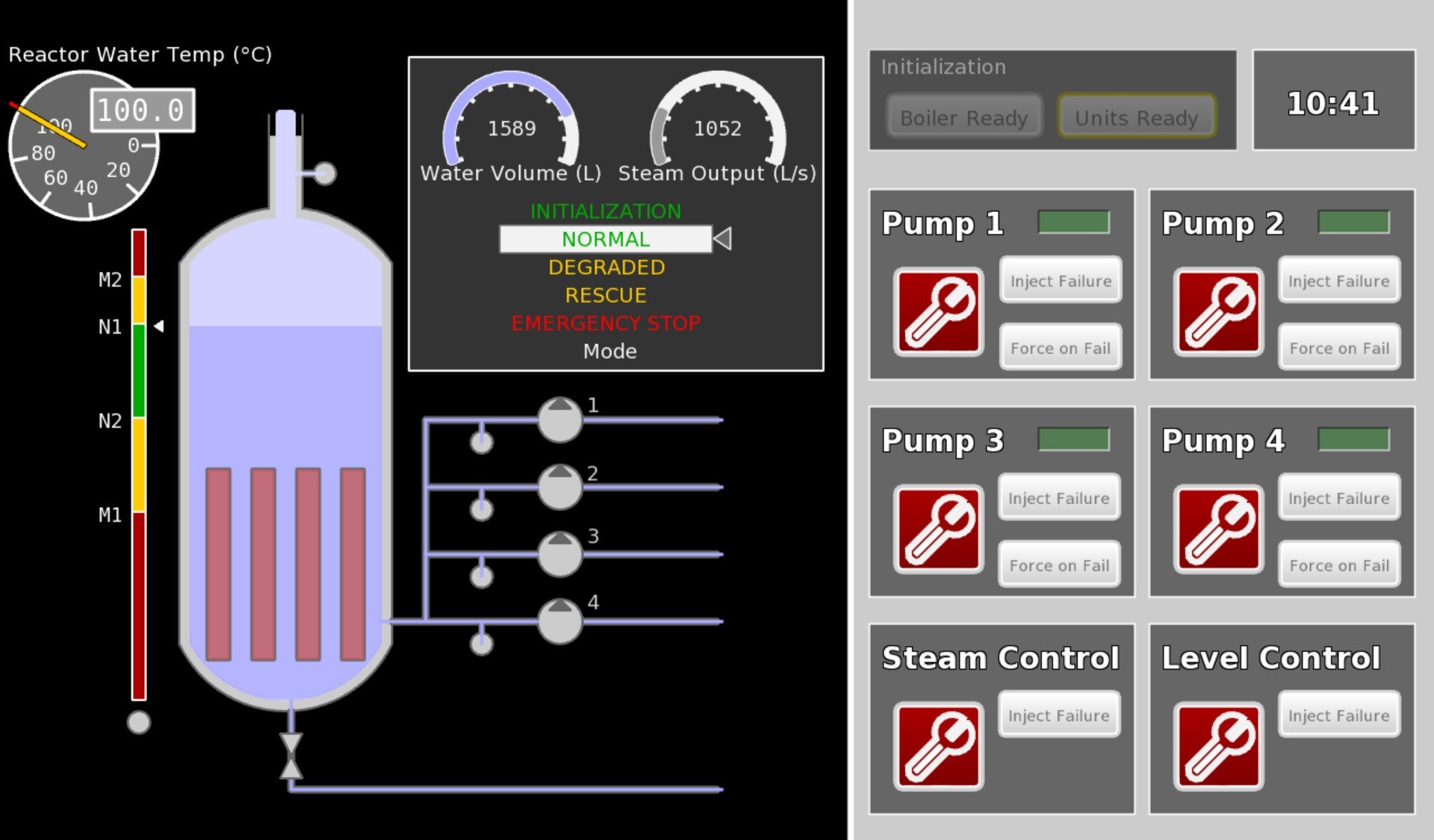
Screenshot of a sample, legacy embedded display panelThe problem space
For this project, we want to design an embedded HMI panel for a smart steam boiler. The boiler uses a heat source (e.g. nuclear fuel) to produce steam. Its software is reactive: it reads sensor inputs cyclically and uses actuators to balance the system within acceptable parameters.
Sensors monitor the outward steam pressure and temperature as well as the inner water level. The actuators are four separate water injection valves. Should anomalies arise such as out-of-bounds sensor data, sensor defects, or valve anomalies, the HMI should display alerts and encourage an operator to act.
In addition to this, the HMI should provide “debugging” functions in the form of buttons that allow injecting failures on-demand on the various sensors and effectors, and suppressing those failures, returning to a normal state. Interactivity is managed through a touch screen, so buttons can be graphical elements.
Collaborative Design
Collaborating with a designer is a crucial first step for this project. The designer’s primary role is to provide expertise in graphical design, user experience and visual aesthetics.
Studying Modern and Futuristic HMIs
With the project’s functional description in mind, the designer delves into the world of modern and futuristic HMIs, not only within the industrial sector but also in fields such as consumer electronics, automotive interfaces and even science fiction films. This broader perspective provides a wealth of inspiration for creating a forward-looking design for the Smart Boiler Control.

Some examples of reference embedded HMIs, real or imaginedCreating a mood board
To guide the design process and align the team’s vision, the designer creates a mood board that visually represents the desired aesthetics and concepts.
The mood board features:- Inspirational images and examples of modern and futuristic interfaces.
- A color palette that matches the intended look and feel.
- Typography choices that convey a sense of modernity and readability.
The mood board will serve as a visual reference and design guide throughout the collaborative process. It helps ensure that all team members, including engineers, developers, and stakeholders, are on the same page regarding the visual direction and user experience goals.
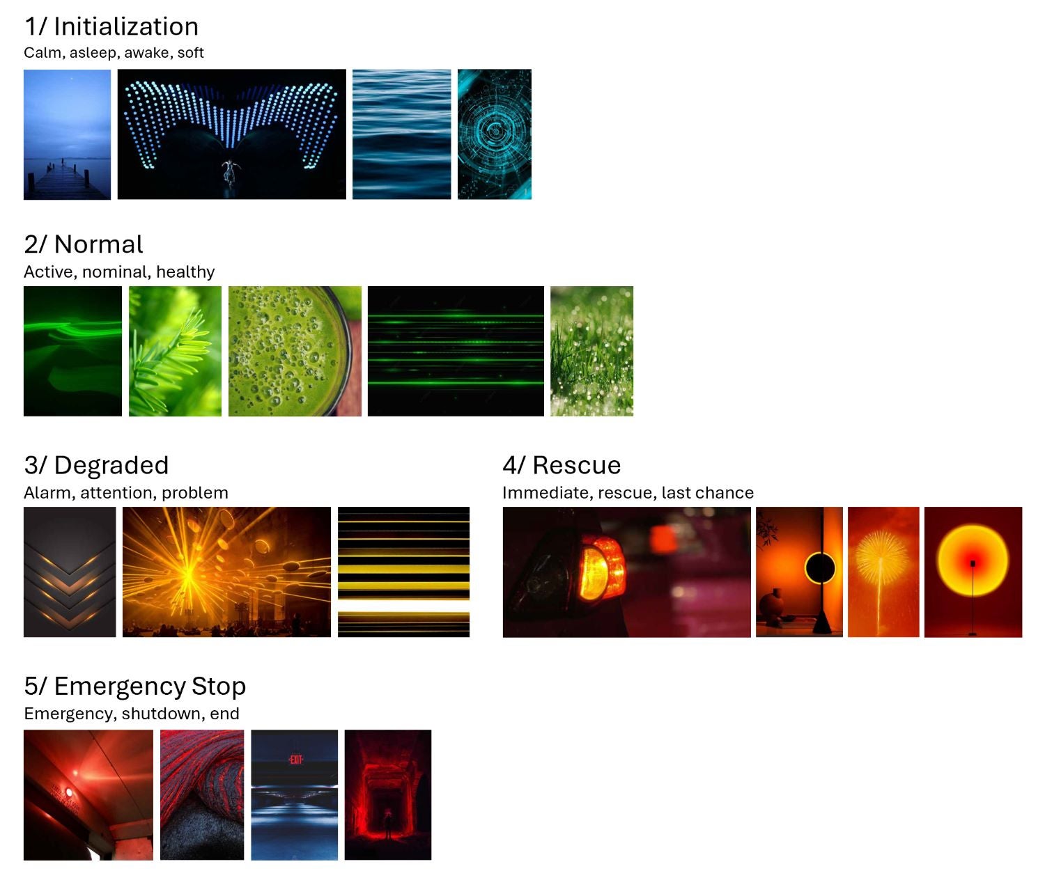
Excerpt of the mood board assembled for this projectAt this stage, the team decides to associate a color to possible states of the overall system.
Iterative Design
The collaborative design process involves several iterations of wireframing, prototyping and visual design reviews. The designer provides his vision in terms of visual elements, color schemes, typography, icons, and layout. Iterations then balance this vision with engineering concerns, until a final design is produced that is both functional and aesthetically pleasing.
Low-fidelity wireframing
The wireframing step begins with the collaborative input of both engineers and the designer. The following aspects are considered:
- Information Hierarchy: determining the prioritization of information and features on the interface. This includes identifying critical data that should be prominently displayed and less important details that could be presented in a secondary manner. After completion of all iterations, the solution was to use color to convey the overall state of the system and to highlight elements relevant to the current state (for instance defective sub-systems).
- Layout and Structure: decisions on the arrangement of elements, such as the tank, mode indicator and buttons, and data representation. The retained solution incorporates a time chart for each key metric of the boiler and a dynamic notification window to focus the operator’s attention onto ongoing issues.
- Element Placement: wireframes are used to position and size elements on the screen, including buttons, input fields, icons, and graphical indicators. The designer’s expertise in ensuring a balance between aesthetics and functionality is instrumental in this process.
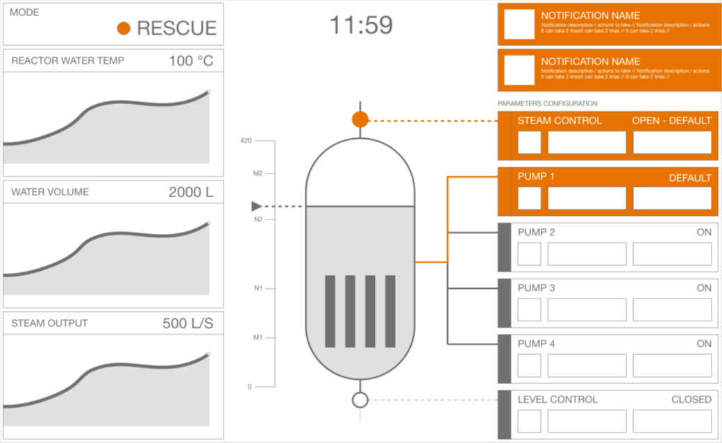
Early wireframes of the new designThis wireframing step plays a pivotal role in the collaborative design process. It provides a structured foundation for the Smart Boiler Control’s interface design, allowing the team to align on the layout, functionality, and user flow. Wireframes serve as a bridge between conceptual design and the creation of a visually appealing, user-friendly, and functional final interface.
At this stage, the team decides to use color with intent in the future design. A single highlight color should convey the system’s overall state. It should also highlight elements of the HMI that are relevant to that state (e.g. notifications or out-of-bounds values).
High-fidelity prototyping and visual review
Now that wireframes are agreed upon, high-fidelity prototyping and visual review can begin. This phase plays a crucial role in refining the design and ensuring that it meets the project’s goals. It allows for the creation of interactive prototypes, based on the wireframes, followed by in-depth visual reviews.
Prototyping with Figma
The prototyping phase involves the following key steps:
- Interactive Prototypes: using Figma‘s interactive features, the designer and engineers transform the wireframes into interactive prototypes. This allows for a realistic simulation of user interactions, such as button clicks and content animation.
- Iterative Refinement: feedback from both engineers and user testing is used to make iterative improvements to the prototypes. This ensures that the interface is both functional and user-friendly.
Visual Review and Feedback
The visual review process is instrumental in ensuring that the redesigned HMI meets the desired aesthetic and design goals:
- Detailed Visual Design: the high-fidelity design, incorporating colors, typography, icons and graphical elements outlined in the mood board, is applied to the interactive prototypes.
- Visual Consistency: The designer ensures that visual elements are consistent across the interface.
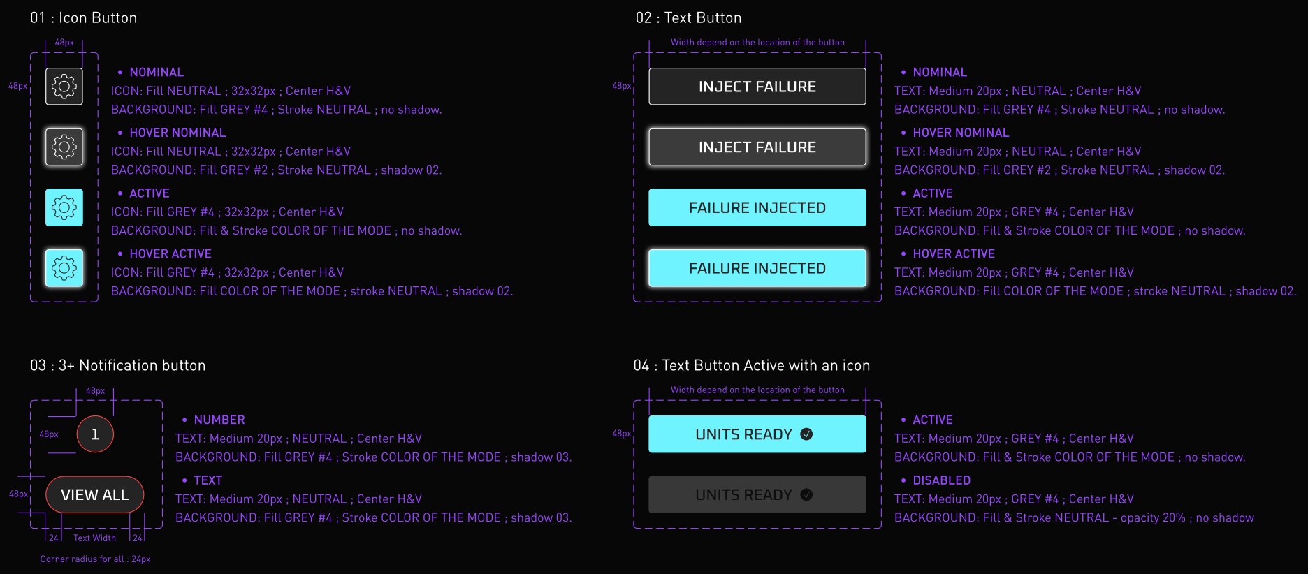
High-fidelity mockups start with defining a unified design language across HMI elementsValidation and Refinement
The prototyping and visual review process allows for thorough validation of the interface design. User feedback from the prototyping phase is integrated iteratively until all parties sign off on the design.
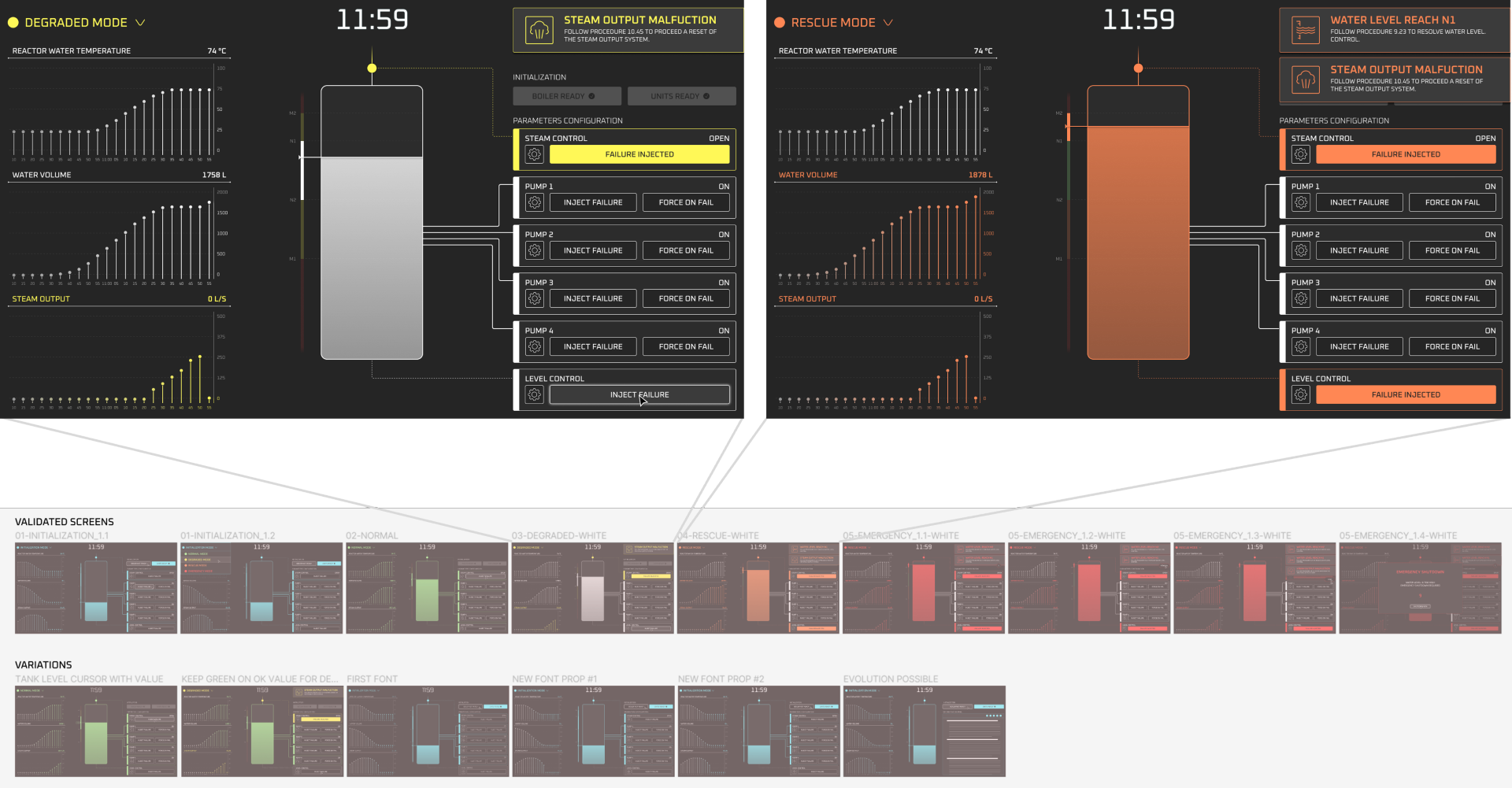
Side-by-side high-fidelity mockups of the new designAs planned in earlier phases, a single highlight color conveys the state of the overall system, while highlighting UI elements relevant to said state. For instance, in the yellow “degraded mode”, color highlights a malfunction with the steam output sensor. In the orange “rescue mode”, additional failures with tank water level controls are highlighted and warrant a heightened alert state.
This guarantees immediate readability of the issues and their severity by an operator.
Handoff for Development
At this stage, design is finalized and validated, and everything is ready to be handed off to the development team for implementation.
The prototyping and visual review process using Figma gives all stakeholders confidence that the Smart Boiler Control interface meets both functional and design goals. This iterative, collaborative approach allows for thorough testing of functionality, user experience and visual design, resulting in an interface that is not only visually appealing but also highly functional and user-friendly.
Stay tuned!
In this blog, we looked at the process of iteratively designing a next generation embedded HMI to control an industrial boiler.
In the next blog, we will focus on the implementation of this design in SCADE Display, to turn these mockups into actual embedded software. We will see how the choice of Figma as a design tool allows engineers to be autonomous in the generation of image assets, with the desired cut-outs, file formats, and sizes. This allows the creation of a pixel-perfect implementation of the designs while minimizing effort and back-and-forth exchanges with the designer.
About the author
Ludovic Oddos (LinkedIn) is a Lead Product Specialist at Ansys. He has been supporting SCADE field engagements, in many industries, for more than 15 years. He has deep expertise in embedded software and its integration into various target environments.
-


Introducing Ansys Electronics Desktop on Ansys Cloud
The Watch & Learn video article provides an overview of cloud computing from Electronics Desktop and details the product licenses and subscriptions to ANSYS Cloud Service that are...

How to Create a Reflector for a Center High-Mounted Stop Lamp (CHMSL)
This video article demonstrates how to create a reflector for a center high-mounted stop lamp. Optical Part design in Ansys SPEOS enables the design and validation of multiple...

Introducing the GEKO Turbulence Model in Ansys Fluent
The GEKO (GEneralized K-Omega) turbulence model offers a flexible, robust, general-purpose approach to RANS turbulence modeling. Introducing 2 videos: Part 1 provides background information on the model and a...

Postprocessing on Ansys EnSight
This video demonstrates exporting data from Fluent in EnSight Case Gold format, and it reviews the basic postprocessing capabilities of EnSight.

- An introduction to DO-178C
- Scade One – Bridging the Gap between Model-Based Design and Traditional Programming
- ARINC 661: the standard behind modern cockpit display systems
- Scade One – An Open Model-Based Ecosystem, Ready for MBSE
- Scade One – A Visual Coding Experience
- Using the SCADE Python APIs from your favorite IDE
- How to Verify a Model on Host with SCADE Test? (Part 4 of 6)
- How to integrate multiple SCADE models into one executable
- Scade One – Democratizing model-based development
- Introduction to the SCADE Environment (Part 1 of 5)

© 2025 Copyright ANSYS, Inc. All rights reserved.


