-
-
December 22, 2024 at 7:14 am
-
December 23, 2024 at 2:09 pm
Kirill
Forum ModeratorDear Subscriber,
It is difficult to provide specific guidance without additional details.
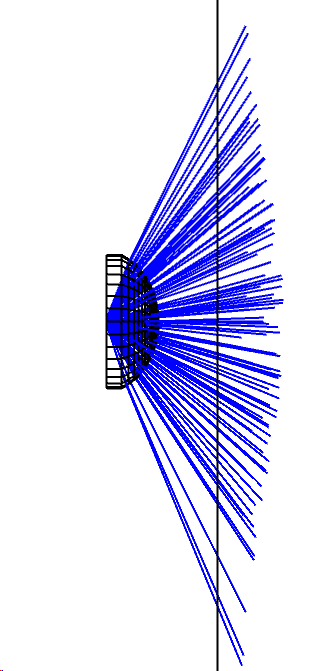
1.What is the optical system, and how did you set the variables?
2. How do you ensure that your system can deliver better performance than it already achieves?
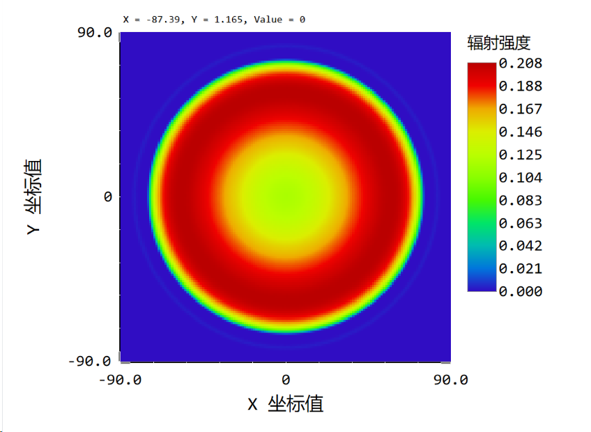
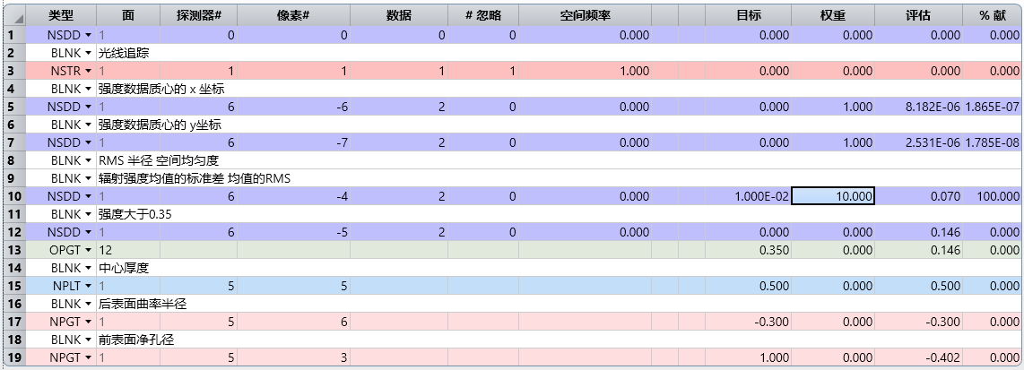
3. NSDD -4 2 gives the RMS of flux per solid angle for all the non-zero pixels in the entire detector, which is square. Your target area seems to be a circle. How do you ensure you are not unintentionally optimizing the corners of the detector as well?Best regards,
Kirill-
December 24, 2024 at 3:19 am
-
-
December 24, 2024 at 12:41 am
-
December 24, 2024 at 3:27 am
-
December 27, 2024 at 2:51 am
Kirill
Forum ModeratorDear Subscriber,
I noticed a couple of things:
1. I can’t read the text in your NSQ Editor, but I don’t see any element in your system that defines the target area. For example, I notice the secondary ring in the detector, and it seems you’re optimizing for that as well. I think you need to include something to clearly define the target area.
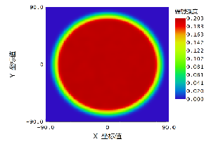
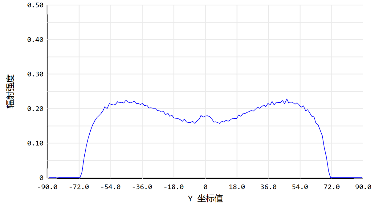
2. It appears the distribution is no longer improving because it may already be the best achievable with the way your system is defined. Why do you think it’s possible to achieve better results?Best regards,
Kirill
-
- You must be logged in to reply to this topic.


-
3407
-
1057
-
1051
-
896
-
887

© 2025 Copyright ANSYS, Inc. All rights reserved.

