-
-
January 25, 2018 at 4:45 am
mikejm
SubscriberI am a hobbyist musician and I have been working on music synthesis models for physical instruments like drums. A snare drum's sound can mostly be reduced to fundamentally three things: (1) Head vibration for which the modes are predicted by the Bessel function zeros, (2) Noise generated by the snare wires, and (3) Ring from the metal drum shell.
It is #3 that I need help with now.
I have been able to find articles which discuss various ways to predict the modes of a thin cylinder using ANSYS, so I know this is possible. But I do not have the engineering or physics background to be able to do it myself (I am medical by formal training/trade).
I have attached a few articles reviewing this. I'm wondering if it would be hard to create a project that could calculate various modes (ie. m,n=1,1 up to say 10,10) based on a given cylinder thickness, radius, and depth, as well as a parameter to specify material properties (eg. aluminum, steel, brass).
I am also wondering if a drum shell would be best simulated as a clamped, free, or simply supported boundary condition.
If anyone would be able to do this for me as a small project, I would be happy to pay what is fair by PayPal. I am stuck with my synthesis project until I get this sorted out.
Thanks for any thoughts or ideas!
Mike
-
January 25, 2018 at 2:11 pm
peteroznewman
SubscriberHey Mike,
That's a great project. I would add to your list (4) Air between the skins. Here is a discussion that has to do with air vibration creating a sound. I read “The Science of Sound” 2nd Edition by Thomas D. Rossing late last year and there is a chapter on drums, so I will borrow that book to reread that chapter. I recall that the air couples the vibration of the top and bottom skins. Also, the frequency of vibration of each skin is highly dependent on the tension in the skin, and the top and bottom skins are deliberately adjusted to different tensions to create the right sound. Are your Bessel functions taking account of the tension?
Another member is trying to predict the acoustics of a violin-like instrument. You can read that discussion. There is another discussion of a very detailed ANSYS question that relates to plate vibrations.
I will be glad to help you on this project.
Regards,
Peter
-
January 26, 2018 at 4:32 am
mikejm
SubscriberHey Pete,
Thanks for your reply and thoughts. In my experience of synthesis, it is not generally necessary to accurately replicate EVERY aspect of an instrument in order to capture its fundamental character. For example, many guitarists fixate on the body of a guitar and what wood it is, etc. but there are beautiful sounding guitars that don't even have traditional "bodies", and in my experience, the string behaviors are the only part that are absolutely critical to synthesize. eg.:
https://www.youtube.com/watch?v=2eEB-vJic_o
Similarly, when it comes to drums, calculating the modes of two drum heads which are tuned differently and "coupled" was far too complicated when I looked at it, and I decided it was probably not necessary. In the 70s, many drummers removed the bottom heads from their toms and bass drums, so they were only one head. And some drums like the Sleishman drums have a floating shell system whereby the two heads always remain in equal tuning. So it is simplest to just consider the head as a "one head" system. Two heads with different tunings can create a pitch bend when struck, and that portion is easy enough to emulate. In my experience, this compromised approach has been sufficient to get the head sound that is desired.
I am already close to finishing on this project. Using some of the published mode relationships for the cylinders in the articles I posted I can already get the general shell "ring" sound I want. But I want to be able to "tune" these frequencies to the standard shapes and materials of a true snare drum to make them more correct.
Would putting together an ANSYS project that can model a thin metal cylinder and predict its modes, eg. from (m,n) of (0,1) to (9,10) be difficult? I would want the following as adjustable variables:
- shell thickness (typically 1 mm)
- radius (typically 7")
- depth (typically 5-6.5")
- material (typically aluminum, steel, or brass)
- if it doesn't change the math too much to be unwieldy, a way to set the edge condition between clamped, free, or simply supported boundary condition so I can test to find which sounds best (but this is less important)
I don't see a PM function on the forum. It might take me months to learn how to do this in ANSYS. By it might take you just hours. If this is something you think you could do for me, please let me know.
I'm dying to get this project finalized so I can put it to use! This is the last part I'm stuck on.
Thanks again.
-
January 26, 2018 at 2:11 pm
peteroznewman
SubscriberHi Mike,
Here is an example of how you could get results from ANSYS. You can type in as many rows as you want.
The bunched up columns are Thickness for each system, I want to replace that with a single parameter for all systems.
Steel is about 3 times stiffer than aluminum, but also 3 times heavier, so the frequency doesn't change that much.
I added a Clamped-Free edge as you wouldn't want free on both ends (though that is possible to compute).
Brass stiffness varies from 102 to 125 GPa, which is a wide range. I can put that in as a parameter to vary.
Here is a video of all the modes from 1 to 40 for the 5 inch tall Steel Clamped case.
At mode 29, you see that a (2,n) mode begins. Before that are the (1,n) modes.
https://youtu.be/CZf6G3j93e0
If you download ANSYS Student 18.2 (not AIM), you can look at the attached model, or I can just feed you results.
To verify that this model gives the same results as shown in the first paper attached, I used Diameter 300 mm and Height 600 mm with a 1 mm Thickness to get a result that matches the data from Lee and Kwak.
Regards,
Peter
-
January 26, 2018 at 8:43 pm
mikejm
SubscriberHey Pete! This is incredible! I can't believe you were able to do that. The past 2 hours since I saw your post, I've just been so excited because I've been so seriously stuck on this part of the synthesis. Reading those journal articles I had no idea how to actually make it happen or how hard it would be. Thanks so much already.
Based on what you've done so far, I'm wondering if it might be possible to:
1) "Re-orient" the format to make it more flexible for material specification.
2) Have all boundary conditions and combinations as options (so I can test to see what sounds best).
3) Have it output a list or table of frequencies up to a given (m,n).
What material parameters are necessary to specify in order to perform the analysis? Is it just Young's Elastic Modulus? Density as well perhaps? If it is just a few simple parameters, perhaps the design could be done like follows:
A few other entry boxes (like density if needed) could be added for setting other required parameters.
If material specification requires too many factors that are too complicated to list (I see you seem to have referenced a materials database in ANSYS), then a dropdown like this might work for material if possible (with also still the same dropdown for boundary conditions):
But ideally if it's just a few parameters that need setting, we could use the first approach, and I could manually set those (ie. Elasticity, Density...) based on reference data for the material. Elasticity data in GPa for metals for example is listed here. Elasticity for woods is on this site. I can manually reference other materials databases as well. This would give me maximum flexibility to experiment with materials.
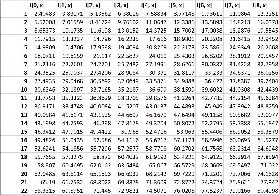
For output, ideally a table like this would be great, but any format where I can see what (m,n) a given frequency outputted is will work. This is for example how I got the Bessel zeros for a circular membrane as an output from Wolfram-Alpha:
What do you think? Are these changes doable?
You've already made my day! Thanks again. Looking forward to seeing if we can make it happen.
-
January 26, 2018 at 8:54 pm
mikejm
SubscriberFor example, using the "first approach" where materials parameters are specified manually could I presume allow the project to be structured as follows:
With just one more "step" for F-SS.
This might keep things from becoming too complex, and as I said, allow me to really tweak and play with different materials.
I don't really know though because this is my first look inside ANSYS ...
Thoughts?
-
January 27, 2018 at 1:44 am
peteroznewman
SubscriberHey Mike, glad you liked that. I figured out how to use one thickness for all systems. Here is a version that includes two material parameter: Density and Young's Modulus and the six boundary conditions you want. There is one other material property, Poisson's Ratio, but it doesn't vary much across all metals and won't affect the frequency in this model.
You might delete the Free case since that is how the structure would vibrate floating in space and there is no drum head. Because of the body floating in space, the first six modes all have zero frequency because they correspond to rigid body motion in three translations and three rotations.
The numerical solution sorts the frequencies into ascending order. It has no concept of a (1,n), (2,n), (3,n) mode shape because it didn't come from a Bessel function input. I think you will have to determine how many axial modes by inspection. Open each Results line item and click on Total Deformation n in the Outline window on the left. I requested 100 modes. The image below doesn't seem to fall into a (m,n) category.
You can copy and paste the frequencies from this table in each Results line. That may be cleaner than adding 100 columns to the Parameter set table.
I will get this example to you so you can play around with it. I will address adding wood material properties in another post. Have fun!
Regards,
Peter
P.S. How many cores are there in your computer? If there are more than 2, then you can spend less time waiting for the solver with a simple configuration. Let me know.
-
January 27, 2018 at 3:35 am
peteroznewman
SubscriberLooking at images of snare drums, I see there several designs that include contact between the tensioner and the side of the drum.
This contact is going to suppress certain modes. For example, contact near the center is going to suppress the (1, n) and (3, n) modes, while having little effect on the (2, n) modes.
Also, the number of contacts around the circumference will have an effect on the other direction. If there are 10 contact points around the circumference, you probably won't see the (m, 9) or (m, 11) modes but the (m, 10) model will still be there.
Adding support or point masses at these contact points can be added to the model, but that may be more specific than you are looking for.
-
January 27, 2018 at 8:50 am
mikejm
SubscriberThanks Pete! This is awesome. Could the wood drums not also be implemented in the same project design, just with different density and elasticity? And/or different Poisson's ratio if it applies here too?
It's a shame we can't get an output of the number of axial or circumferential mode number for each one. But I can understand if that's not possible. Certainly this is still taking me very close to an ideal result. I should be able to match up at least the m=1 modes manually by visual inspection as you say.
The reason it is important for me to be able to determine the mode # corresponding to a given frequency is that I need this information to roughly guess how "present" in volume each mode should be. I do not have data to establish how rapidly the modes decline in volume as you go up, but I presume the vast majority of the modes present will be simple m=1 circumferential modes with a rapid decline as you go up in "n" values for this. I doubt the m=2 modes are even significantly present when you have the heads pressing down on the shell and the shell is relatively short compared to its diameter. I am guessing m=3 is almost not represented at all.
But the point is I need to be able to match each frequency to its modal number in order to try approximating this higher mode ~ lower level relationship. The problem with doing it by visual inspection is once you get to modes like (3, 5), I expect it's going to be impossible to figure out what I'm looking at.
What you say about damping from the hardware attached to the drum makes sense and absolutely that's the case in real life. The beauty of synthesis though is you don't have to follow real life! This is similar to what I was mentioning earlier about guitars and figuring out from trial and error what matters and what doesn't. The same effect of mode suppression occurs with real guitars based on where you pick them, and also where the pickups are situated. But I find emulating this does not add to the simulation - to the contrary it takes away from it.
In this shell synthesis, I therefore want to have a case where the shell is completely floating and no modes are suppressed.
As a point of interest, I actually own a set of Sleishman drums which are designed in this exact way. The top head and bottom head are held on by hoops which are connected by a "cage" which does not contact the drum shell itself in any way. It's a pretty neat design, but has both pros and cons musically:
I will play with the project you have made for me tomorrow. Thanks again so much. If you can come up with a good way to adapt this for wood shells as well I'd very much appreciate it too. And I'm not holding my breath, but if you can figure out a way for ANSYS to figure out which mode number each frequencies corresponds to, that would save me a lot of manual work, and help me go into the higher "m" modes without getting lost.
-
January 27, 2018 at 9:12 am
mikejm
SubscriberOn the subject of approximating the volume to which each mode should be set compared to another, I just had another thought.
Perhaps an even better way to do this would be if ANSYS could tell us how much energy it would take or how difficult it would be to excite each mode. If it can tell us that, this would tell us how proportionately present each mode should be, in a far better way than just guessing based on how comparatively high the m and n are for it.
I'm just brainstorming because I don't know what ANSYS is capable of. Could it output some measure of this next to each frequency that I could use to judge how loud that frequency should be represented from?
Thanks again.
-
January 27, 2018 at 7:58 pm
peteroznewman
SubscriberHey Mike, I'm glad you're enjoying this!
I have been studying mechanical and acoustic vibration for the last couple of years, reading books, building models in ANSYS, learning to use accelerometers and microphones, analyzing data, etc.
One lesson I learned is that most of the energy is in the lowest mode of all the modal frequencies. There are exceptions, such as when a harmonic force is applied to the antinode of a second or third mode, then that mode will have the most energy.
For example, a drum head can be hit at the center and excite the (0,2) and (0,3) modes, while it can also be hit off center and excite the (1,1) and (2,1) modes.
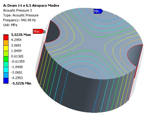
Contrast this to the sides of the drum which are mainly exited by the air pressure inside the drum. ANSYS has an analysis called Modal Acoustics. I attached a model of the airspace inside a 14 x 6.5" drum. The model assumes the walls are rigid, so this is not a coupled solution with flexible skins. It calculates how the air itself can support a resonant frequency, just based on the shape of the walls. I have attached an example of that.
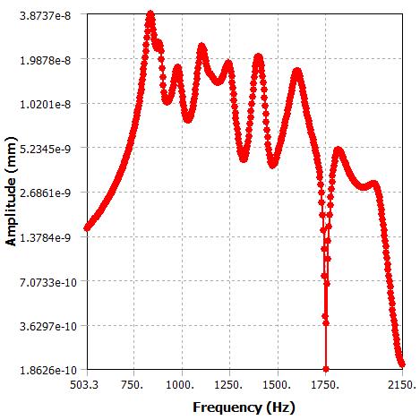
ANSYS has an analysis called Harmonic Response. That applies a harmonic force or pressure to a face, edge or point and calculates how the structure will respond (harmonically) to that force. I applied a harmonic pressure to the drum side wall and looked at the response of one point at the center of the wall. I have attached an example of that also. Here is the amplitude of the motion of that point on the center of the side wall, plotted against the harmonic frequency of the pressure on the wall (imagine a speaker inside the drum that can play different tones to apply a sinusoidal pressure to the side walls).
See how the largest amplitude is the lowest frequency? See how at 1750 Hz, there is a huge dip in the response.
That matches mode 42 (the answer to life, the universe and everything) where there is a nodal line at the center.
I have more to say about the properties of wood, and your other comments, but I have to go now.
Regards,
Peter -
January 28, 2018 at 12:08 am
mikejm
SubscriberHey Pete,
This is all fantastic. Thanks so much for your time and effort on this. Your skill and experience are invaluable to me.
I can see after getting more comfortable in ANSYS that it's actually going to be quite easily to manually count the modes, as things can always be reoriented, so that is no longer an issue. For example, like this:
I have one further question, if you don't mind answering when you have some time.
When you pluck a string, or hit a drum head, then yes, absolutely the lowest (m,n) mode is strongest, and it is also lowest in frequency. As you go up in "n" on either instrument, the frequency goes up and the volume goes down.
But a cylinder seems to have different behavior.
When considering the (1,x) series, for example, we can very rapidly see that lower "n" modes can actually have higher frequencies. For example contrasting what I think is (1,6) with (1,30) - please tell me if I'm counting these wrong (maybe these should be called (1,3) and (1,15)?) - we see the lower "n" mode has a higher frequency than the higher mode:
Would you still expect the (1,6) to be louder than the (1,30)? Intuitively, I would expect it still is. It just goes against the "pattern" I'm used to from synthesizing strings and drum heads.
As a further example, this mode doesn't show up until #98, which I think is (1,1) - is this the correct name of it?
Would you still guess guess that this should be the most fundamentally loud mode compared to the others?
Thanks again. I still can't believe you did this for me. If you can help me with adapting this for wood shells, that would be fantastic, since I can then add the same shell modelling to my tom and bass drum synths.
Either way, tonight or tomorrow I'll work on doing audio tests, based on the traditional principle of making lower "n" modes louder and higher "n" modes quieter, and I'll update based on what I find.
-
January 28, 2018 at 12:21 am
mikejm
SubscriberAlso I just notice two little funny issues with the current project.
1) Every mode is duplicated
1=2, 3=4, 5=6, etc.
So only the "odd" (or even) modes are necessary since the evens are duplicates of the odds.
2) Need to be able to add modes
I'm noticing on the Simply Supported model (which might be most interesting because the frequencies really cover a broad spread), that I can't even find the (1,1) mode among the 100 (ie. 50) modes calculated. I tried duplicating a Deformation and setting the mode to 101, but it told me it's out of boundary when I tried to calculate it.
How would I go about adding modes to this project, eg. if I want them to go up to 200, or 500 and thus allow me to find those most fundamental modes, which may be quite high in frequency?
Thanks again and no rush to get back to me. I really do appreciate your time. This would be impossible for me without your help already.
Cheers and hope you're having a good weekend.
Mike
-
January 28, 2018 at 2:49 am
peteroznewman
SubscriberHey Mike, I'm having a great weekend, thanks. Wow, you have made some progress with ANSYS!
One tip for orienting the view, you can click on the X, Y or Z parts of the triad in the lower right corner to orient the view.
2) More Modes: It's easier to show you how to change the number of modes in a video.
https://youtu.be/J7ufcLCZl9o
Follow these directions to solve on 4 cores instead of 2 cores and cut your wait time down by nearly half.
1) Duplicate Frequencies: Yes, you do get duplicate frequencies in the solution. Just ignore them.
Here is the way the circular plates are listed in the book, Springer Handbook of Acoustics, Thomas Rossing, Editor.

A CD-ROM came with the book and they play those 12 tones one after another, then they play all the tones together and it kind of sounds like a drum. I guess that is what you are trying to do. I added those two WAV files into a zip file and attached it to this post.
The first number is the count of radial nodes, and the second number is the count of nodal diameters.
For the cylinder, the paper uses this convention:
So the #39 above with the frequency of 1751 Hz would have (m,n) = (1,3), and #98 would be (1,1) with a frequency of 2836 Hz.
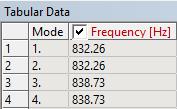
The solver sorts the natural frequency results from lowest to highest. The cylindrical shell lowest natural frequency is (1,
 at 832 Hz while the (1,4) shape has a frequency of 1387 Hz, so you are counting them right.
Surfaces create sound by the velocity they impart to the air particles at the surface. In a previous post, I showed the displacement response of one point on the surface as a function of frequency. I could have shown the velocity response instead. It turns out the velocity is larger at the higher frequencies.
But this is just for one point. What you want is to let every point on the surface create a pressure wave and put a microphone at some distance and measure the loudness. Well, the ANSYS Harmonic Acoustics system can do that. How awesome is that! I know it's possible, but I have not yet learned how to do that, though I plan to struggle through the learning curve soon.
Damping as a function of frequency is also a critical aspect of creating a good synthetic sound. I include a paragraph from the Kettle Drum (Timapani) section.
I should have time to write about wood tomorrow. It is far more complex than metals.
Regards,
Peter -
January 28, 2018 at 7:22 am
mikejm
SubscriberWell, I ran the simulation. I did a 14x5" steel 1.2 mm snare with 300 modes and simply supported boundaries. Went through them counting manually and putting them into a spreadsheet by (m,n).
Then did some rudimentary level shaping based on (m,n) with synthesis.
Final outcome: Sounded like a metal drum shell being "tapped", which is exactly what I needed for it to be. As with all synthesis, it does not need to be scientifically perfect - it just needs to sufficiently resemble the acoustic phenomena it is modelling.
So I will consider this component of the synthesis now essentially solved. Thank you again so much.
Any thoughts on how to do this for wood? Couldn't we just use the same modelling but input wood based constants?
eg. Maple wood:
http://www.wood-database.com/hard-maple/
Elastic modulus 12.62 GPa
Density: 705 kg/m3
You said the third coefficient needed was Poisson's Ratio, which was similar for all metals, but I presume not all woods as well. I can find some Poisson's Ratios for wood listed here:
http://www.atcp-ndt.com/products/materials-characterization/material-properties/property-tables/wood.html
If that will work, can you perhaps add a Poisson's Ratio field to the "parameters" section and I can enter wood vs. metal constants as needed?
Thanks.
-
January 28, 2018 at 1:40 pm
peteroznewman
SubscriberThat's great that the metal drum shell sounds right.
Most metals have properties that are the same in all directions (isotropic) and only need two parameters to describe the stiffness: Young's Modulus, E, and Poisson's Ratio. The Shear Modulus, G, needed to complete the stiffness description can be calculated from these values.
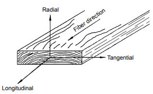
Wood has properties that are different in each direction (orthotropic) and need nine parameters to describe the stiffness. The directions are along the grain: L, in the radial direction where the rings grow: R, and transverse to the grain: T So there are three Young's Modulus values: EL, ER and ET, three Poisson's Ratios and three Shear Ratios. There is a way to create that material in ANSYS. Here is a good paper on wood properties.
What you need to define is what directions in the wood grain (L R T) are aligned with the drum shell. Is L along the axis? Is R through the thickness? Is T along the circumference? If the wood shell is made of plywood, then you have to know how many plies and which direction the L property goes in each ply.
The other factor is metals have very low damping. That is they will ring for a few seconds when tapped. Wood is more heavily damped and the vibration from a tap will decay rapidly in a fraction of a second. You can probably shape the decay profile with your synthesizer, but the damping causes the natural frequency to shift from the undamped natural frequency.
Best regards.
-
January 29, 2018 at 7:48 pm
peteroznewman
SubscriberHey Mike, here is another model to play with in ANSYS, it is the mode shapes of a simply supported circular plate. I know you have your Bessel function that can create that, but I just wanted to build this model for fun. Mathematically, you can multiply the Bessel function by the tension to get the frequency, but in ANSYS, you have to apply the tension to the material before you calculate the mode shapes. Therefore, there is a Static Structural system A where the temperature goes down from the initial temperature of 70 down to 60 or 50 degrees F. The drum skin material has an artificially large coefficient of thermal expansion so when the temperature goes down a little, the tension in the drum skin goes up a lot. The tension in the skin is measured in psi. The display of Equivalent Stress has only one value. Then when you go to the Modal solution, you can see all the shapes from the literature. I have't checked the frequencies yet.
Regards,
Peter
-
January 31, 2018 at 4:33 am
peteroznewman
SubscriberWood for Drum Side Wall
To simulate the mode shapes and frequencies of a material like wood requires a cylindrical coordinate system and a small APDL code snippet to assign the cylindrical coordinate system to the shell element coordinate system. In the figure on the left, you can see that Z is radial, Y is longitudinal (axial) and X is tangential. Without the command snippet, the element coordinate system is random and not useful as shown in the figure on the right.
The properties of wood are listed according to this convention:
If we assume a drum side wall is fabricated by steaming a sheet of wood to wrap it around the drum diameter with the grain running axially and the rings through the thickness, an orthotropic material can be created to follow this fabrication.
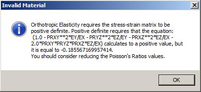
Below is an orthotropic material property for a wood. Note that the Young's Modulus in the X direction is an order of magnitude larger than in the Y or Z directions.
The largest value of Young's modulus for wood is always in the L direction, along the grain, and in the model described above, that is the Y axis but the material shown in this table has the largest value in the X axis. I just have to swap the values in this table to line up with this model's element axis.
-
February 4, 2018 at 6:15 am
mikejm
SubscriberHey Pete,
Thanks again! That's very cool, and I can see why wood becomes more complex.
Can you have it set up with the grain running vertically like this, as if you hollowed out a solid treetrunk?
Ideally let's also say if we can, that it's hardwood solid maple:
http://www.wood-database.com/hard-maple/
Sorry for the delay in getting back. Been swamped with work and other things. Still very eager to try to make this work if possible.
Looking forward to anything you can share.

-
February 10, 2018 at 1:21 am
peteroznewman
SubscriberHey Mike,
A hollowed out solid treetrunk is the ideal construction to match the wood material properties I wrote about above.
I referenced this paper, which is very detailed, but I also had to make some adjustments to have a set of properties that meet the requirements of the orthotropic material model.
The values were adjusted until the material became valid.
Wood properties are often listed by the directions of the grain: Longitudinal, Tangential and Radial. Those directions were mapped to the element coordinate system shown in the post above so that Longitudinal = Y, Tangential = X and Radial = Z.
The Modal Analysis is created for many combinations of boundary conditions: Simply Supported, Clamped and Free and alternating combinations of those for each end of the drum side.
Wood is going to be much thicker than metal, so the initial wall thickness is 0.25 inches. The metal drum archives previously could change all systems from the parameter set. Not sure why, but this archive doesn't update the thickness across all six systems. Each of the six systems that feature different boundary conditions have a thickness that is changed individually in the Mechanical software for the sheet body.
These models calculate the natural frequencies of the drum side wall, but a very significant difference between wood and metal is the very large difference in damping of the material. When a metal drum side is tapped, the structure will "ring" for a little while. When a wood drum side is tapped, the ringing of the structure dies out much more quickly. That is not represented in the modal frequencies. That would have to be included as part of the synthesis of the sound.
Best regards,
Peter
-
February 9, 2019 at 1:45 pm
kravky
Subscriber
The tension in the skin is measured in psi. The display of Equivalent Stress has only one value. Then when you go to the Modal solution, you can see all the shapes from the literature. I have't checked the frequencies yet.
Regards,
Peter
I would like to ask You if You checked that the frequencies are in the agreement with the literature. I mean if you change the boundary condition from simple support to fixed, You should get following result for freq.:
2nd_mode= 1,59*1st_mode
3nd_mode = 2,14*1st_mode
4th_mode = 2,30*1st_mode
and so on, according to the analytical solution for transverse vibration of ideal circular membrane, clamped on its boundary: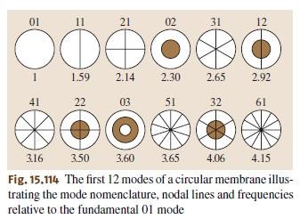
I tried to change it, but i didnt get right solution.
Thanks,
Adam.
-
February 9, 2019 at 1:58 pm
peteroznewman
SubscriberHi Adam,
Please copy this post and paste it into a New Discussion. It's best to "own" the discussion you are posting in. This is someone else's, so you can delete the post above once you have done that. You can reference a particular post in someone else's discussion by RMB on the #Permalink word under the post, Copy Link Address and use the Link button in the toolbar to paste the link over one of the words in your post like I did in the previous line here.
Regards, Peter
-
August 22, 2020 at 4:37 pm
Nihad
SubscriberHello Peter,nI am working on calculating mode shapes of a clamped-clamped thin- walled plate. I am looking for a hiring somebody for that . are you okay help me with my work?.ihad n -
August 24, 2020 at 3:51 pm
peteroznewman
SubscriberHello Nihad,nAre you able to put your model up on this public site? If so, please open a New Discussion and I can help you.nPetern
-
- The topic ‘Work for hire: Calculating the vibration modes of a thin metal cylinder (ie. Snare Drum)’ is closed to new replies.


- LPBF Simulation of dissimilar materials in ANSYS mechanical (Thermal Transient)
- Real Life Example of a non-symmetric eigenvalue problem
- How can the results of Pressures and Motions for all elements be obtained?
- BackGround Color
- Contact stiffness too big
- Element Birth and Death
- Python-Script to Export all Children of a Solution Tree
- Which equations and in what form are valid for defining excitations?

-
4597
-
1495
-
1386
-
1209
-
1021

© 2025 Copyright ANSYS, Inc. All rights reserved.


-aluminum-clamped.jpg?width=690&upscale=false)


