TAGGED: boundary-layer, dpm-boundary-condition, steadystate, thickness
-
-
January 31, 2026 at 9:35 pm
gny24002
SubscriberHi,
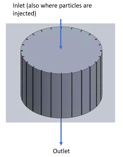
I am trying to measure the velocity and concentration boundary layer thickness of particles from dpm injection in a cylinder:


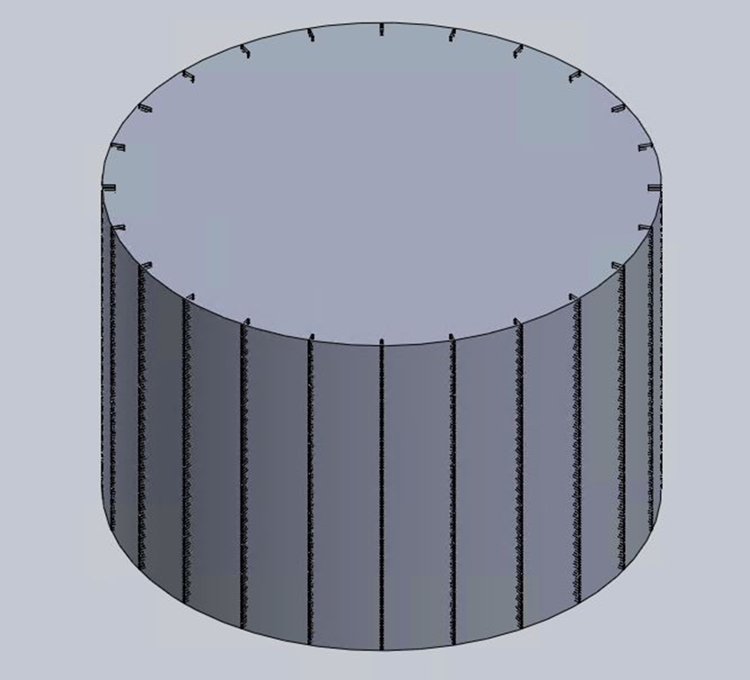
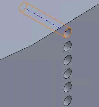
The cylinder has internal protrusions on the surface of the wall. Flow is in the axial direction from the top to bottom and gravity acts perpendicular to the direction of flow. No slip boundary along with trap boundary condition is applied at the wall of the cylinder along with the protrusions. At first a steady-state flow is simulated in the cylinder for approximately 450 iterations until convergence is reached. This is done to establish a flow inside the cylinder before injection since the velocity of the flow is around 10E-5 m/s (laminar flow regime). After the steady-state flow, dpm injection is applied at the inlet for 1 iteration, this too is for steady-state. In cfd-post, a 2D plane is generated in the axial direction and four lines are drawn from the tip of one protrusion to the opposite side containing the other protrusion:

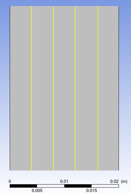
Around 200 data points are taken from each each line and the radial distance vs axial velocity is plotted:

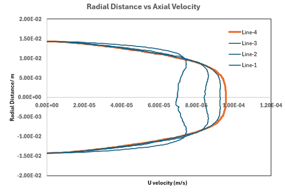
The data points from line-4 are considered and the distance from the tip of a protrusion to the point where the velocity is 99% and 95% of the maximum radial velocity is measured. The corresponding values at 99% and 95% thresholds turn out to be ~1 cm and ~0.8 cm. But if you look at the velocity surface plot these numbers might not be accurate:

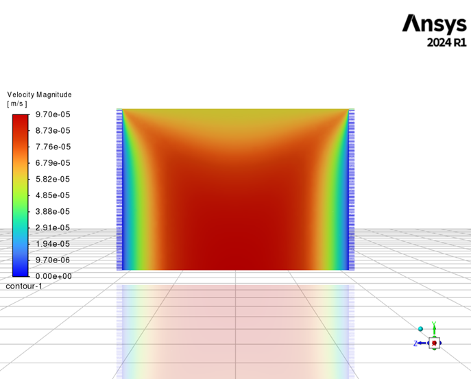
The radius of the cylinder is approximately 1.5 cm. If the boundary layer thickness based on 99% and 95% threshold are incorrect, what is the correct way to estimate the boundary layer thickness in this case?Â
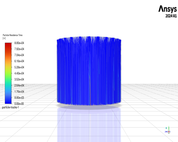
Lastly, the following are the particle residence times for different sized particles:For 300nm:
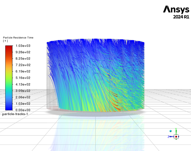
For 300nm most of the particles leave the domain due to stokes law where gravity has negligible effect whereas for 10 micron, almost 30% of the partciles have been trapped. Now, based on the retention of particles, how can one determine the concentration boundary layer thickness?Â
Thank you!! -
February 2, 2026 at 2:01 pm
Rob
Forum ModeratorIf you're looking at boundary layer thickness in the flow, you can plot velocity on lines across the domain and look for a velocity threshhold based on your definition for boundary layer. That's easier done in Fluent. But make sure the mesh is adequate: is the domain long enough?
Why are the smaller particles moving in the -z direction? If you're releasing from all of the fins equally I'd expect a more uniform distribution.Â
-
February 4, 2026 at 10:16 pm
gny24002
SubscriberHi Rob,
Thank you for your reply. To clarify, the DPM injection is from the inlet (not from the protrusions). The bulk flow is in the axial direction (top to bottom). Gravity is applied in the −z direction in my coordinate system. So when you apply stokes law, gravity has negligible effect on 300 nm particles compared to the larger 10 micron particles.
The following shows the 2D plane containing lines drawn along different distance along the axial direction:

Again the velocity inlet is at the top and the dpm injection also occurs at the inlet and not at the wall.ÂFor the velocity boundary layer: I initially plotted axial velocity along wall-to-wall lines (from a protrusion tip to the opposite protrusion tip) at multiple axial locations and applied a 95%/99% threshold. However, since this is low-Re internal flow, I realize a 99% criterion referenced to the maximum velocity along a full diameter line can give a thickness comparable to the radius. In that case, for a cylinder how to accurately measure the velocity boundary layer thickness if we don't want to apply the same 99% or 95% criterion that is generally applied for flow over a flat plate?
The channel length is 2 cm and the cylinder diameter is 3 cm (L/D ≈ 0.67).Â
One additional question: for a DPM case with wall trapping enabled, what is the recommended way to define and measure a concentration boundary layer thickness near the wall/protrusions? In Fluent/CFD-Post, would you suggest using a particle concentration/number-density field (if available), post-processing particle tracks into near-wall bins, or solving a separate scalar transport (species) field to quantify the near-wall concentration layer? I want to make sure I’m using a definition that is standard and defensible.
Thank you again for your guidance.
-
February 5, 2026 at 9:55 am
Rob
Forum ModeratorNot as simple as you think. I'm also limited in what I can say as I'm working under rules from Legal.Â
DPM Concentration is defined in the manual, but note, as it's cell and parcel mass based it's a useful number but not necessarily for what you want.Â
For a flow boundary layer you'd plot velocity with distance from the wall and there will be a reference text book somewhere with criterion. It's not something I've had to worry about since University, and not something we covered in much depth there as we were more worried about the reacting chemicals escaping from the pipes....Â
The accretion model may be sufficient to measure particle contact under trap conditions. The Eulerian Wall Film can also be abused in this way - turn off film momentum. The "best" way is via a UDF as you need to add parcel mass into the cell. Remember DPM particles have no volume so there is no shielding effect.Â
-
- You must be logged in to reply to this topic.
-
5274
-
1859
-
1403
-
1257
-
1021
© 2026 Copyright ANSYS, Inc. All rights reserved.


