-
-
September 27, 2021 at 1:42 am
rcl5011
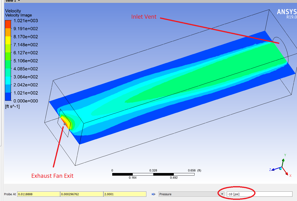
SubscriberI need to simulate cooling an electronics assembly using Fluent. There will be a fan on the outside of the enclosure drawing air out of it. The inlet is just a louvered area. I need to know how large this louvered are needs to be in order to allow the fan to run at maximum flow rate. I have a fan curve, but when I enter the fan info into the pressure jump box, my solution results always have extremely high velocities, almost an order of magnitude larger than what the fan can do at the given pressure. What am I doing wrong here? I need to have the fan velocity kept in check by the iterated pressure head it is seeing based on the calculations for losses through the inlet louvers. Right now it just jumps to max pressure head, and the corresponding velocity through the fan is extremely high.
My pressure jump parameters using piecewise linear are:
1) 0ft/s @ 10psi
2) 5ft/s @ 5psi
3) 10ft/s @ 0psi
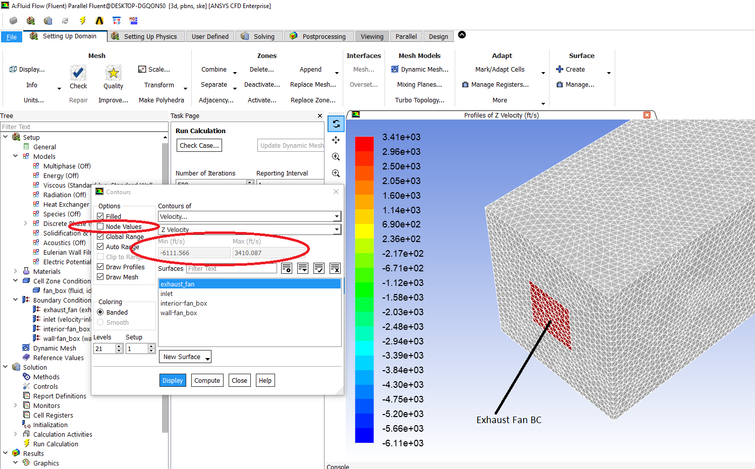
My results are shown below when probed at the exhaust fan outlet:
September 27, 2021 at 10:08 amRob
Forum ModeratorCheck the result in Fluent, and plot the velocity with node values off. That way we can check if it's a true or interpolated maximum. Also check the panel sees psi etc or Pascals: some of the Fluent models assume SI units. Finally, I'm not sure how zero is seen in the solver, set the 0 psi value as 0.001 psi and repeat.
September 27, 2021 at 1:56 pmSubscriberThanks Rob. I'll try these suggestions out this evening and re-run the simulation. I will report back my findings whether successful or not.
September 27, 2021 at 11:29 pmSubscriberI have re-run the simulation with the following scenarios:
1) Imperial units with .001 in place of zero
2) SI units (converted from imperial and manually entered), with zeros in place
3) SI units (converted from imperial and manually entered), with .001 in place of zero
All three of these produced the same results, which is that my fan velocity exceeds what my pressure jump curve should allow by greater than an order of magnitude. After switching back to imperial units for simplicity of my data, I unchecked node values, and the results still show 3,400ft/s velocity, where my fan curve limit is 10ft/s at zero psi.
I'd love to see an example of someone using this fan curve pressure jump setting successfully. I figured this would be a simple exercise to implement. I'm not sure how else I can efficiently do this simulation with the electronics cooling without a lot of manual trial and error work entering things manually.
Any other suggestions from Rob, or is there anyone else that has done this? All comments are greatly appreciated!
September 28, 2021 at 12:42 pmForum ModeratorHow's the convergence? Put a velocity inlet (negative value) on the outlet and a pressure on the inlet and see how it behaves.
September 29, 2021 at 12:23 amSubscriberI put a velocity inlet on the outlet with negative value. It worked, although convergence isn't all that great. Pressure on the inlet isn't ideal because I need the pressure as a function of geometric conditions of my enclosure. I am going to manually iterate it at this point. I can't spend anymore time trying to get this fan curve to work. It's actually a real shame for how expensive this software is. I am going to just use a mass flow rate on the outlet. Knowing how many watts of power the electronics are putting off and the expected flow rate of my fan, I can know the density of the air entering the fan, and hence the flow rate. I will then check the pressure drop and make sure it is less than required for my fan flow rate (mass flow rate). If the pressure exceeds the fan curve, I will increase inlet are geometry on the enclosure until my pressure drop is less than the pressure drop at my given outlet flow rate (from fan curve). It will take more manual work, but that's where I'm at now. I'd love to have someone comment on how to use these fan curve pressure jump parameters properly, so if anyone has an answer on how to use Exhaust Fan boundary conditions properly please let me know for future application. Thanks!
September 30, 2021 at 1:01 pmForum ModeratorIf a negative velocity isn't converging that suggests that something else is going on. How's the mesh quality and are the other settings sensible?
October 3, 2021 at 2:18 pmSubscriberSo what is the point of inlet/outlet boundary conditions if they can be used interchangeably? Is there truly no benefit to using an inlet BC on and inlet, and an outlet BC on an outlet exclusively? Using an inlet velocity on the outlet would be ideal instead of mass flow, being that mass flow is dependent on the temperature, and that is something I don't fully know until the solution is done, at which point I need to itterate. I will work with Inlet velocity on the outlet for now and see where I get.
Similar question to above. If I use an inlet on the outlet, must I use an outlet on the inlet, or can I use an inlet on the inlet and an inlet on the outlet? In simpler terms, must an inlet be paired with an outlet, or can you use inlets/outlets exclusively together?
Thanks!
Viewing 7 reply threads- The topic ‘Understanding Fan Boundary Conditions’ is closed to new replies.
Innovation Space Trending discussions
 Top Contributors
-
peteroznewman
 4929
4929 -
scabo
 1618
1618 -
Dennis Chen
 1386
1386 -
javat33489
 1242
1242 -
Shyam Prasad V Atri
1021
Top Rated Tags
© 2026 Copyright ANSYS, Inc. All rights reserved.
Ansys does not support the usage of unauthorized Ansys software. Please visit www.ansys.com to obtain an official distribution.
-

Fluids
Topics related to Fluent, CFX, Turbogrid and more.
Understanding Fan Boundary Conditions


Ansys Assistant

Welcome to Ansys Assistant!
An AI-based virtual assistant for active Ansys Academic Customers. Please login using your university issued email address.

Hey there, you are quite inquisitive! You have hit your hourly question limit. Please retry after '10' minutes. For questions, please reach out to ansyslearn@ansys.com.
RETRY