-
-
January 2, 2018 at 10:08 pm
simsek8
SubscriberHello,
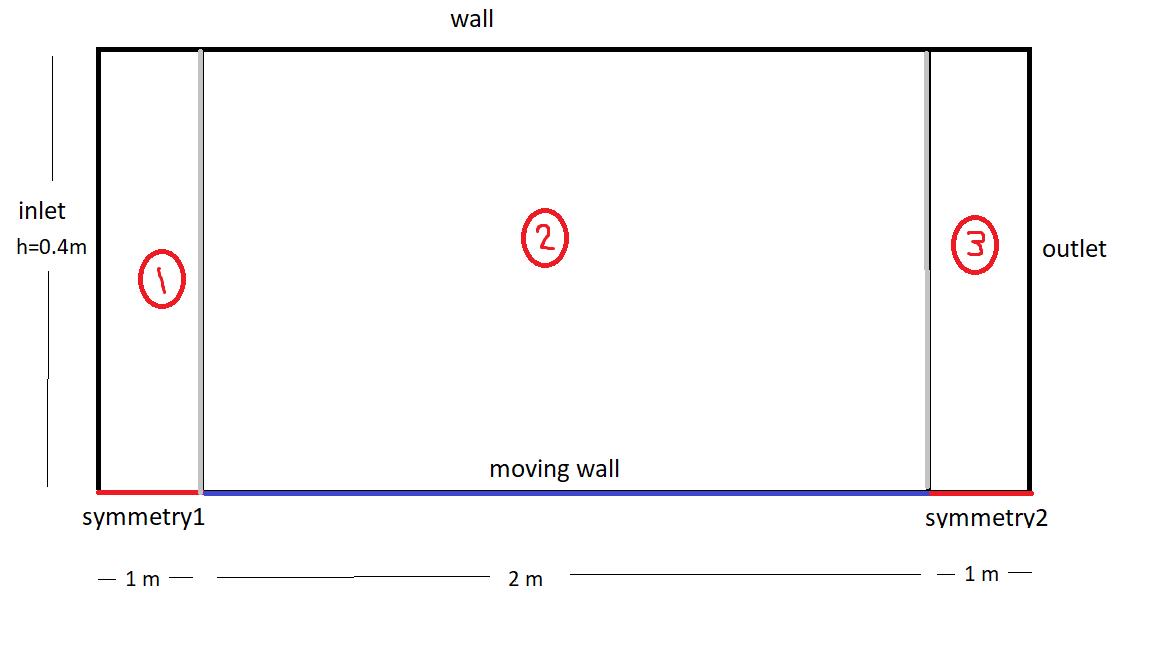
A thin plate moves between two parallel surfaces as in figure:
I want to find drag force onto moving wall.
Length is 2 m.
h1 = h2 = 0.04 m
There are two regions. They are same(h1=h2). So this problem might be considered as 'semi lid-driven cavity' problem. But only one difference: Inlet and outlet are not wall. Therefore I encounter reverse flow error.
I drew a rectangle and let the south boundary to moving wall(absolute 5 m/s), north boundary to wall, east boundary to wall and west boundary to wall. Eventually I failed.
Any idea how to solve ?
Regards.
-
January 3, 2018 at 12:53 am
peteroznewman
SubscriberI'm a novice at CFD, but I believe you can benefit from using symmetry in this problem. I drew a 3 m long x 0.04 m tall rectangle in DM and sliced it at 0.5 m from each end so I could have 3 segments, the top three edges were named wall, the bottom was named symmetry on the first 0.5 m, moving wall on the 2 m long segment and symmetry on the last 0.5 m edge. The left and right edges had inlet and outlet names.
You don't say what the fluid is, that would be useful to calculate a Reynolds number.
I assumed air and I got reverse flow messages, but it still seemed to converge.
I found a first order momentum setting gave better convergence.
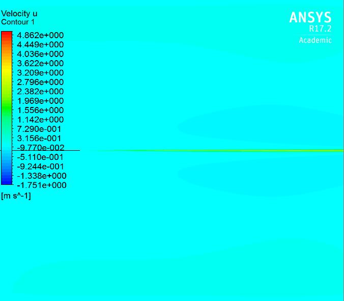
Here is the leading edge after using Reflection in CFD-Post:
Here is the trailing edge...
The calculator in CFD-Post says the Area Integral of Wall Shear X on movingwall = -14 [N]
You would double that for your answer since this is a half model.
I hope a member with more CFD experience replies, since I'm just learning CFD.
Reply with your email if want this 17.2 archive. The Attach button is not working.
-
January 3, 2018 at 11:04 am
simsek8
SubscriberThank you very much. My fluid properties is imaginary. Density is 1000 kg/m^3. Dynamic viscosity is 0.9 Ns/m^2. By the way the moving_wall moves 10 m/s instead of 5m/s.
I still encounter reversed flow. I set 2D Space : Planar, not axisymmetrical. Because if I set it so, it says 'Floating point exception'.
-
January 3, 2018 at 11:41 am
simsek8
SubscriberSome images to clear misunderstandings:
Dynamic viscosity is 0.9 Ns/m^2 and density is 1000 kg/m^3.
Thanks to the horizontal symmetry, I drew the geometry in DM as you said:
I've done the mesh part.
If I choose 2D Space: Axisymmetric, initialization gives me Error: floating point exception Error Object: #f
If I choose 2D Space: Planar, initialization is OK. But it doesn't converge. It always gives me famous reversed flow error.
Thank you again.
-
January 3, 2018 at 3:50 pm
peteroznewman
SubscriberAxisymmetric symmetry means there is an axis of revolution and walls are revolved around that axis 360 degrees. If the wall is horizontal, that creates a pipe. A line body on the axis represents a wire with no area. That is not what you want.
Planar symmetry means the sketch is extruded in the Z direction. The symmetry boundary acts as a mirror. The extrusion is infinite, but calculations are performed on a unit depth (1 m in your case). So a line body 2 m long has a shear force calculated per meter of extrusion depth.
On the Reference Values, I put a unit value in for every parameter. That then created a Cd that is equal to 2 x Drag Force (N) which is perfect since it is a half model. I saw the Cd nicely converging, even though the solver was reporting reverse flow.
Do you get an Error that stops the solver, or are you getting reverse flow messages during the solution?
-
January 3, 2018 at 4:59 pm
simsek8
SubscriberI get reverse flow messages. It doesn't converge.
-
January 4, 2018 at 11:41 am
Vishal Ganore
Ansys EmployeePeter, I appreciate your efforts to this problem.
Blockmesh, here are some suggestions:
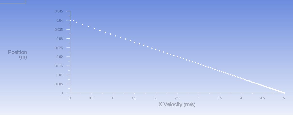
1. Please decide whether you have a laminar flow or turbulent flow (It looks like you have to go for laminar flow, highly viscous fluid (0.9 Ns/m2, I assume fluid is stationary, calculated Re is close to 1000. For internal flows, if Re<2000,flow would be laminar). Looks like it is a classic case of Couette flow (please see verification test case 004 under Fluent manual)
2. If you treat your flow to be turbulent (unlikely) then please investigate your mesh and suitable turbulence model. Y+=1 for all turbulence models and sub-types is not recommended. Near wall function defines your range of recommended Y+ value. More info is available in Fluent manual.
3. Boundary conditions: you can't treat inlet and outlet as walls, Instead I would go with periodic boundary condition?
4. Only solve half of the case with planer condition. I would not take symmetry edge in my geometry. If taken, please treat symmetry edge as a wall in boundary type and provide same plate velocity (just to avoid modifying geometry again)
5. Wall shear stress X area of plate = drag force, so you could focus on calculating wall shear stress (Tw) (N/m2) across plate.
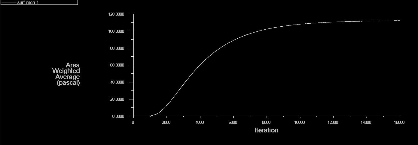
6. Theoretical Tw (per Newtons law of Viscosity) = dynamic viscosity*velocity/distance between two plates = 0.9*5/0.04= 112.5, for your case Tw=112.5*2=225.
-
January 4, 2018 at 11:49 am
-
January 4, 2018 at 12:05 pm
-
January 4, 2018 at 4:36 pm
peteroznewman
SubscriberHi Vishal, thanks for this detailed reply. I am learning CFD, so I make that disclaimer when I provide suggestions, some of which are correct but some are not. I deleted my previous post that was prematurely marked as the solution. I expect your first post above can be marked as the solution.
-
January 5, 2018 at 2:55 pm
Raef.Kobeissi
SubscriberHello Tou can also use a dynamic mesh for the moving thin plate in the fluid domain. -
January 5, 2018 at 3:14 pm
simsek8
SubscriberThank you vganore,
1. Please decide whether you have a laminar flow or turbulent flow (It looks like you have to go for laminar flow, highly viscous fluid (0.9 Ns/m2, I assume fluid is stationary, calculated Re is close to 1000. For internal flows, if Re<2000,flow would be laminar). Looks like it is a classic case of Couette flow (please see verification test case 004 under Fluent manual)
Yes, you're right. I learned yesterday that it is called Couette flow which has no pressure gradient. For turbulence, Re=1000*10*0.04/0.9=444 which is laminar.
5. Wall shear stress X area of plate = drag force, so you could focus on calculating wall shear stress (Tw) (N/m2) across plate.
Exactly.
3. Boundary conditions: you can't treat inlet and outlet as walls, Instead I would go with periodic boundary condition?
4. Only solve half of the case with planer condition. I would not take symmetry edge in my geometry. If taken, please treat symmetry edge as a wall in boundary type and provide same plate velocity (just to avoid modifying geometry again)
Periodic boundary is the perfect solution. I solved via periodic BC, it gave me same shear stress number that I obtain analytically. So it is perfect.
-
January 5, 2018 at 3:14 pm
simsek8
Subscriber
Hi Vishal, thanks for this detailed reply. I am learning CFD, so I make that disclaimer when I provide suggestions, some of which are correct but some are not. I deleted my previous post that was prematurely marked as the solution. I expect your first post above can be marked as the solution.
-
January 5, 2018 at 3:16 pm
simsek8
SubscriberHello, Tou can also use a dynamic mesh for the moving thin plate in the fluid domain.
Thank you. But it will make much more complicated. Periodic BCs (inlet and outlet), moving-wall and stationary top wall is fine for simple Couette flow.
-
- The topic ‘Thin Plate Moves Between Two Parallel Plates’ is closed to new replies.


- JACOBI Convergence Issue in ANSYS AQWA
- Is it able to solve turbomachinery using density-based solver in Fluent?
- Two-way FSI simulation
- Ensight Force_per_unit area_EV
- RIBBON WINDOW DISAPPEARED
- Fluent Meshing Error when .dsco not .stp
- Ansys Fluent for modelling Ocean Wave reactions to Wave Barriers
- Battery Pack cooling
- ISAT ABORT error
- UNASSIGNED INTERFACE ZONE DETECTED FOR INTERFACE…

-
4597
-
1495
-
1386
-
1209
-
1021

© 2025 Copyright ANSYS, Inc. All rights reserved.


