-
-
January 23, 2025 at 9:25 am
318661
SubscriberGood morning,
I need some help in order to understand better why in my model I get very high temperatures compared to temperatures measured in reality.
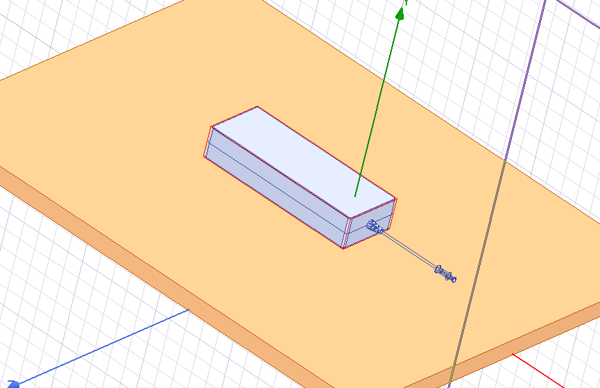
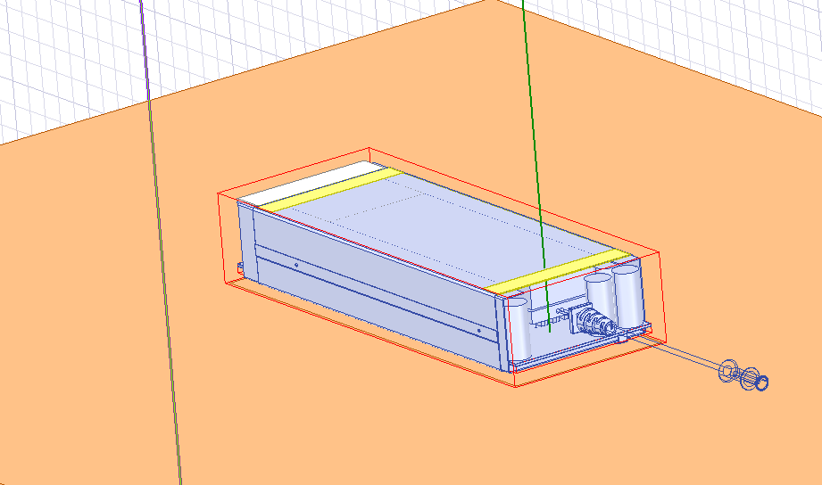
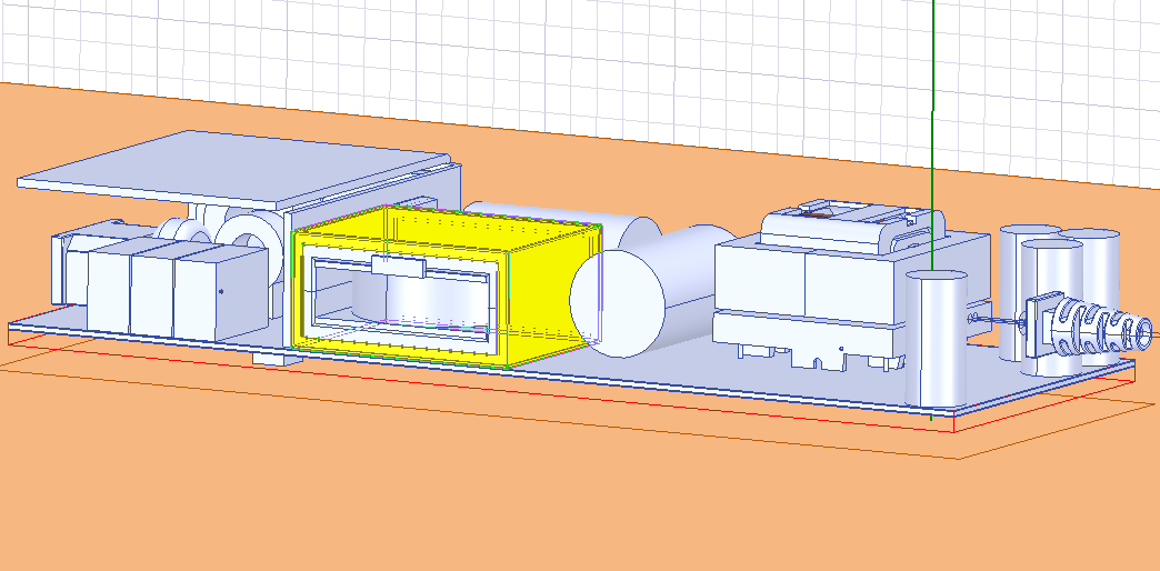
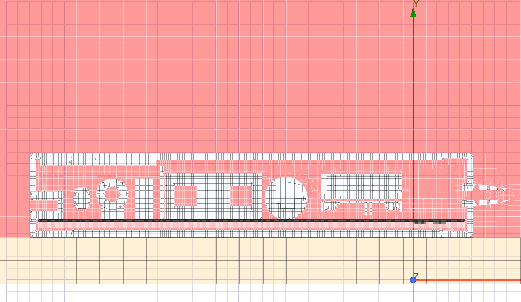
On ANSYS Electronics Desktop (Icepak design) I'm trying to solve the conjugate heat transfer due to natural convection between PCB and electrical components (which are inside a plastic case) and the air, both internal and external. I will share also some pictures to better calrify the situation.Â
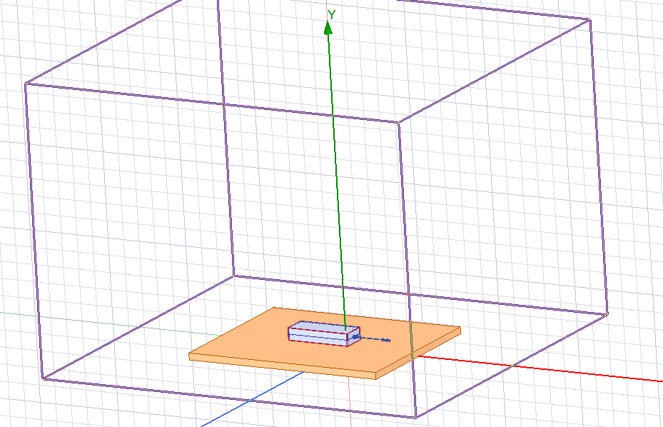
The setup of the simulation is the following:
I built up a domain big enough to simulate natural convetion
I used 2 refinements for the mesh: a box that includes all the case, internal air, upper components ecc, and another box that includes only the PCB and the components mounted on the bottom.
Boundary conditions: all walls with fixed temperature (ambient temperature);
Initial Conditions: Vx = 0; Vy = 0.001 m/s (opposite to the gravity along -y); Vz = 0
Losses in [W] on different components using the "Block" model
For the setup, I followed suggestions the "natural convection default", that is: the simulation is a steady-state, laminar flow, radiation is on (discrete ordinates model), ecc. (basically I didn't change the natural convection default)
The problem, as I mentioned before, is that when the simulations starts, it is a bit unstable (as it can be seen from the diagrams) and final temperatures are pretty high. I was wondering if there was a setup problem somewhat (maybe boundaries), or if there is something I'm missing.
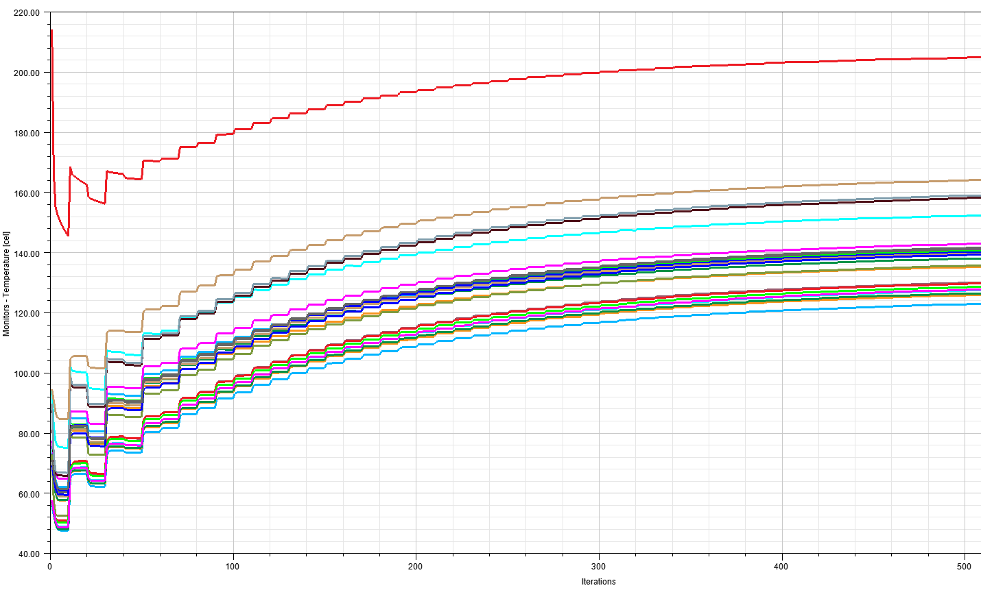
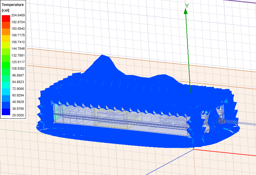
Temperature plot on the "region"
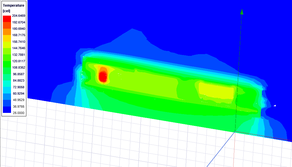
Temperature plot on a cross section
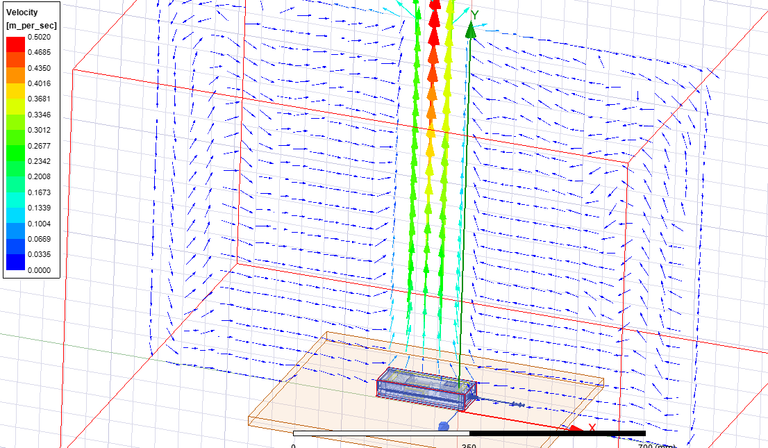
Velocity plot on a cross section
I would be very grateful if someone has any suggestion or is able to help me. Thank you so much!Â
-
January 28, 2025 at 4:52 pm
Iceman
Ansys EmployeeThanks for asking questions on Forum. For the PCB, did you import ECAD onto it? Thanks.-
January 28, 2025 at 5:15 pm
318661
SubscriberThank you a lot for replying! No the PCB and the wole design come from an MCAD file (a step) made in Solidworks
-
January 28, 2025 at 5:18 pm
Iceman
Ansys EmployeeWhat thermal conducitivity did you use for the PCB? PCB has metal layers and heat path between metal layers through vias. If you use an uniform thermal conductivity for the PCB, the heat path will not be accurately represented.
-
January 28, 2025 at 5:40 pm
318661
SubscriberWell, the PCB is modeled with 4 layers of coppers separated by 3 layers of FR-4. (1 layer of copper, than 1 layer of FR4 ecc.)
Thermal conductivity of GR4 is set as isotropic as first try
-
January 28, 2025 at 7:18 pm
Iceman
Ansys Employeeare those metal layers just solid blocks or actually traces? Are there vias connecting different metal layers? Thanks.
-
January 28, 2025 at 7:37 pm
318661
SubscriberYes, they are just solid blocks one on the other, without vias
-
January 28, 2025 at 7:43 pm
Iceman
Ansys EmployeeÂ
You may need to use proper ECAD for the PCB. Please check our training material on Ansys Learning Hub about ECAD modeling.Â
For your model, all heat sources are in a plastic case. There is little air movement inside the plastic case. So the conduction paths inside the case are very important for the temperature prediction.Â
Please also review surface material properties (emmisivity). Radiation is also quite significant in natural convection problem.
The model is quite complex. If the temperature is still too high after these steps, please submit a support ticket. Thanks.
Â
-
January 28, 2025 at 8:14 pm
318661
SubscriberThank you very much for the help! I will try to import the corre ECAD model of the PCB, but still I don't understand why I have such High temperatures... They are more or less all 40/50°C the value measured experimentally, so maybe I am simplifying a bit the conduction thermal path, but I don't expect a huge differenze with respect to reality... Could be any other thing that should be improved?
-
January 28, 2025 at 9:17 pm
Iceman
Ansys EmployeeThe velocity vector looks ok. So the problem is probably conduction path. Please review the model to identify the main conduction paths and make sure they are correctly modeled. As I said in previous thread, if the issue persists, you are welcome to open a support ticket. Thanks.
-
January 28, 2025 at 11:10 pm
318661
SubscriberI will try to review and adjust the model as you suggested... Thank you again for the help!
-
-
-
- You must be logged in to reply to this topic.
-
6234
-
1906
-
1457
-
1308
-
1022
© 2026 Copyright ANSYS, Inc. All rights reserved.


