-
-
January 6, 2023 at 6:53 pm
Zhoubin NI
SubscriberHello, For some reason images are not getting loaded so I respost it.
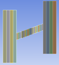
We are working on a project that is doing the tensile test simulation with explicit dynamics to see the fracture in Ansys Workbench. Our project is work on the DLP printer so the geometry in the simulation is layer by layer method with varying angle
We have some equations about it.
1. The relationship of displacement. When we use different values of displacement, the position of fracture is different.
2. the difference between explicit material and other material (What is the necessary data for the tensile test?)
We use formlab clear resin in actual printing but we can't find out the material in 'Engineering Data'. There is some catalog of material in the Engineering Data show below.
. Is the explicit material required to the explicit dynamic simulation or we could do the simulation with material not in the list of explicit material?
3. The connection (is the connection of each component working well like the actual printing?)
The Ansys Workbench automatic connects each component with a type of connection :bonded.
Is the 'bonded' work for the simulation as the connection of DLP printing?
The DLP 3D printer uses UV exposure light to curing the resin layer by layer.
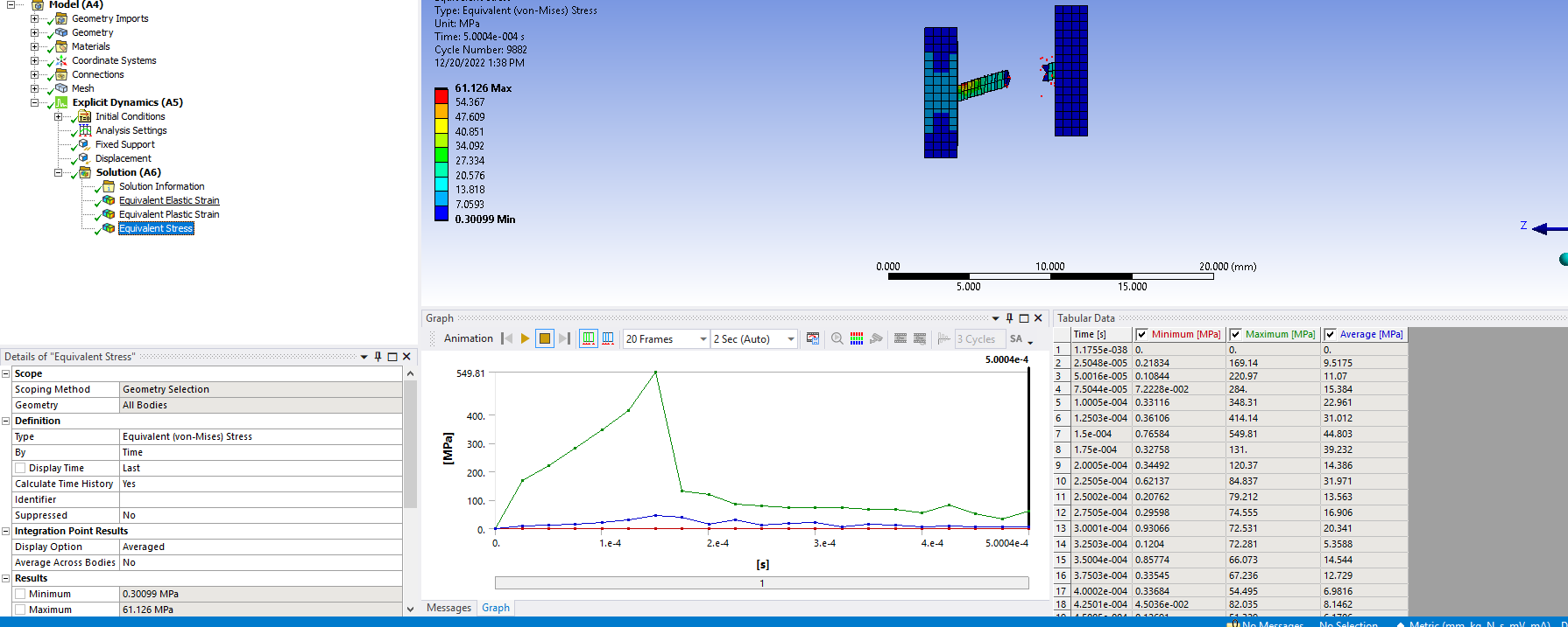
4. The data of the stain looks weird. The data of the equivalent plastic strain is 0 and the trend line of the equivalent elastic strain is the same as the equivalent stress. Which strain should I use?
Thanks in advance.
-
January 9, 2023 at 6:37 pm
Chris Quan
Ansys EmployeeFIrst of all, if you observed different results when different displacements are used in a Displacement boundary condition, can you look at End Time in Analysis Settings? Is the End Time the same between these two analyses? If yes, velocity resulted from the Displacement BC is different. It is possible to observe different material behavior if the materials have different velocity and thus result in different dynamic response.
It is OK to pull material properties from different sources and then use them in Explicit Dynamics system. If you want to model "fracture" as mentioned in your post, you need to make sure Failure Model is included in the material properties. When Failure Model is included, material will fail (fracture) when stress/strain has reached its maximum value. This is very critical to get the accurate representation of the material behavior. Failure model can be added from Toolbox in Engineering Data.
The default contact type is set to Bonded if the distance between material interfaces is within the pre-defined tolerance. You need to check each automatically-created contact region to make sure they are needed and represent the actual motion occured at the material interfaces. If you are trying to model the 3D printing and the new layer of a resin material is printed and settled on the existing material, bonded contact is the reasonable representation of the connections.
If the materials in your model donot include any plasticity and just have linear elastic material properties, the material behaves elastically only. Its plastic strain is zero. If you add material plasticity and failure model to the materials, you should be able to observe non-zero plastic strain and material failure if the resulted stress/strain is high enough.
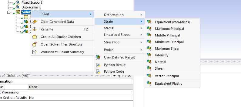
To plot plastic strain, the user-defined results Effective Plastic Strain is the more appropriate variable to use, since it is the one used by Explicit Dynamics solver. Equivalent plastic strain is primarily used for MAPDL solver in other Mechanical Analyses such as Static Structural & Transient Structural analyses.
-
January 30, 2023 at 9:20 pm
Zhoubin NI
SubscriberHello, another question about the connection
When you choose the connection as bonded, how could you change the interfacial energy?
Thanks!
-
-
October 21, 2023 at 2:05 pm
Desi Gustiani
SubscriberHallo Mr Chris, If you are willing can you help me? I really appreciate your help. I want to carry out a tensile test simulation with AISI 4140 material. For the tensile test, does the Explicit Dynamic option use "Force" or "Displacement"? Thankyou so much.
-
October 23, 2023 at 1:35 pm
Chris Quan
Ansys EmployeeEither Force or Displacement boundary condition can be used. Just make sure the loading is applied gradually and slowly to minimize the kinetic energy incurred.
-
-
- The topic ‘Tensile Test’ is closed to new replies.


- At least one body has been found to have only 1 element in at least 2 directions
- Error when opening saved Workbench project
- How to apply Compression-only Support?
- Geometric stiffness matrix for solid elements
- Frictional No separation contact
- Timestep range set for animation export
- Image to file in Mechanical is bugged and does not show text
- Script Error Code:800a000d
- Elastic limit load, Elastic-plastic limit load
- Element has excessive thickness change, distortion, is turning inside out

-
1406
-
599
-
591
-
555
-
366

© 2025 Copyright ANSYS, Inc. All rights reserved.


.png)
.png)
.png)
.png)
.png)
.png)


