-
-
January 21, 2025 at 9:31 pmnm20004Subscriber
Hello, I'm trying to model a composite overwrapped cylindrical pressure vessel in Ansys Acp. I create the stackup sequence for each dome and the cylindrical part separately. First of all I model the alluminum liner for the tank as a whole, then I model the plies [10/-10/10/-10] for the dome at the negative orientation of longitudinal x axis of the global coordinate system, then the plies [10/-10/10/-10/90/90/90/90/90/90] for the cylinder and finally the same plies for the positive dome as for the negative one.
When I solve my model in static structural and I define element orientation I get this message ''Some Element Orientations will be ignored in the solution process due to overlapping elements from Imported Plies''. I don't know what I'm doing wrong in Ansys Acp. Do you have any idea?
Thank you in advance for your help!
-
January 22, 2025 at 5:52 pmRaman BabuAnsys Employee
Can you please try to generate the solid model in ACP Pre and share the snapshot?
Here, I see the issue with the orientation selection sets & ply layup definition.
- Please review the ply reference direction for each orientation selection set
- Also, please examine the ply layup definition. You should create a layup as it is done physically.
-
January 22, 2025 at 11:41 pmnm20004Subscriber
Hello Mr. Raman. Thank you very much for your response!
I generated the solid model in ACP for element set ''All elements'' and global drop-off material CFRP. I selected CFRP because I had to select one material in this field to generate the solid elements but my liner is made of aluminum.
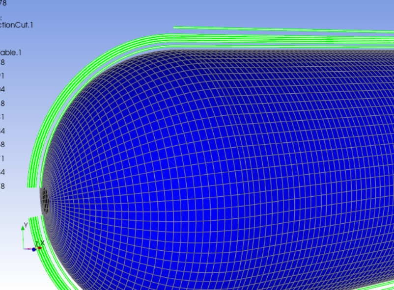
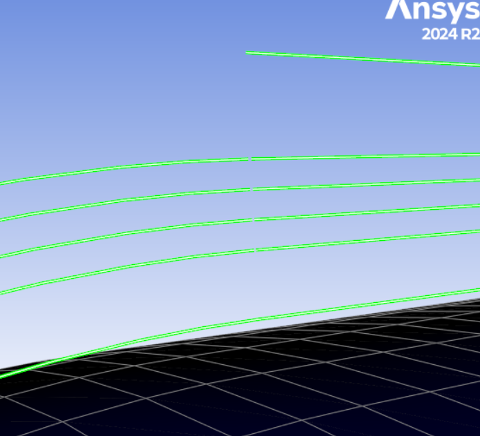
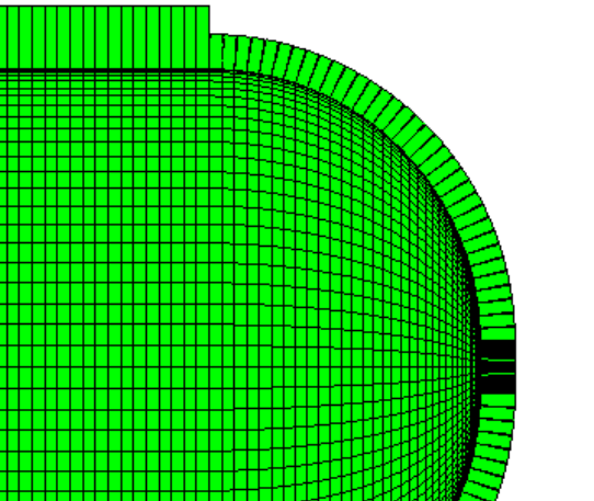
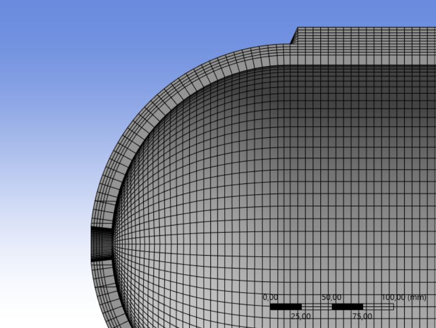
Here is a screenshot for the longitudinal section of my solid model when I transfer it into static structural. The first ply is the aluminum liner and the others the composite plies.
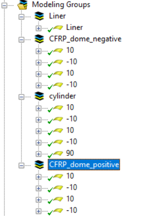
Moreover, I want to describe you the method which I follow in order to define the ply layup. I use a cylindrical rosette and the reference direction for the definition of the winding angle of the fibers is the longitudinal axis of the tank (0 degrees). Firstly, I create the liner as a hoop layer (90 degrees). Then for each of the plies of 10,-10,10,-10 degrees, I create 3D LookUpTables in order to define the change of the winding angle along the domes (non-geodesic tragectories). For the first dome I use the LookUpTables for 10,-10,10,-10, for the cylinder i define the plies 10,-10,10,-10,90,90,90,90,90,90 by defining the angle manually, without LookUpTables and finally for the second dome I follow the same process as for the first one. The coordinates x,y,z of the LookUpTables are the coordinates of the surface of the mesh (the internal surface of the liner). For all the plies, I use offset from the internal part towards the external part of this surface with the aim to define the oriented selection sets (one OOS for each dome and one OOS for the cylinder).
-
January 24, 2025 at 1:04 pmnm20004Subscriber
I noticed another error in my model. Defining the surface of the hemispherical cap of my tank, I set an OSS perpendicular to the surface to create the layer thickness in the radial direction, which is correct. However, when the layers are created, the radius of the opening increases, while it should remain constant from a manufacturing perspective. Practically, a triangle is missing from the layer that I’m pointing out.
The result I must achieve for my project is the below:
I have no idea how to solve this problem and your help would be invaluable!
-
-
January 24, 2025 at 5:13 pmRaman BabuAnsys Employee
You can use extrusion guidelines to extrude the solid model along a specified CAD surface as shown below.
Also, please try to keep a coarse mesh around the cap region. Please check Ansys help on more information on the extrusion guide. 2.1.16.1. Solid Model
Regards,
Raman Babu
-
January 24, 2025 at 8:06 pmnm20004Subscriber
Thank you for your help! In my project I must use shell elements. Is there a possible way to do so with shell and not solid elements?
-
January 25, 2025 at 1:51 pmRaman BabuAnsys Employee
For the shell, It is not needed.
-
- You must be logged in to reply to this topic.
-
1897
-
807
-
599
-
591
-
366
© 2025 Copyright ANSYS, Inc. All rights reserved.