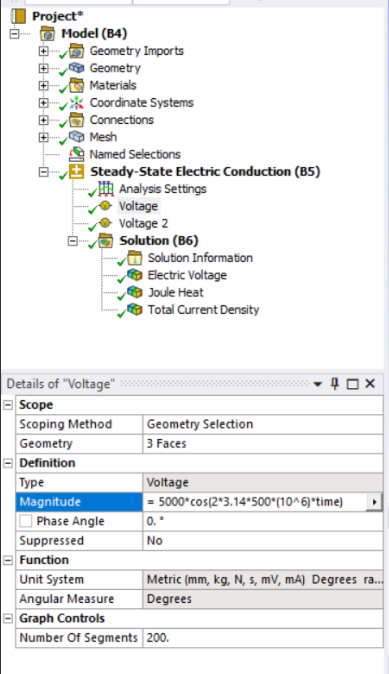
Is your objective to define a square or trapezoidal wave form rather than a sinusoid? If so, you could add a command object containing the following. Append to the end of it the command to assign the voltage to a face, i.e.,
d,V_face,volt,%V1%
where V_face is a component name assigned to the face to which the time varying trapezoidal voltage waveform is to be applied.
Also, put an empty command object under the Solution branch in the tree. A plot of the voltage waveform should appear under it after you solve.
C***************************************************
C*** PARAMETERS DEFINING VOLTAGE TRAPEZIODAL WAVE
C***************************************************
V_ampltd=100 ! AMPLITUDE OF APPLIED VOLTAGE
frqncy=0.1 ! FREQUENCY
P=1/frqncy ! CORRESPONDING PERIOD (DO NOT EDIT)
t_rise=P/20 ! RISE TIME
t_dwell=P/4 ! DWELL TIME
t_fall=P/15 ! FALL TIME
nprds=5 ! # OF PERIODS
t_final=nprds*P ! END OF TRANSIENT (DO NOT EDIT)
C***************************************************
C*** DEFINE TRAPEZIODAL WAVE
C***************************************************
*dim,V1,table,4*nprds+1,,,time ! DIMENSION ARRAY TO HOLD TRAPEZOIDAL WAVE DATA
*dim,keytimes,,4*nprds ! KEYTIME ARRAY FOR TSRES IF THIS IS A THERMAL TRANSIENT
*do,i,1,nprds ! PLACE DATA IN ARRAY
V1(4*(i-1)+1,1)=0
V1(4*(i-1)+2,1)=V_ampltd
V1(4*(i-1)+3,1)=V_ampltd
V1(4*(i-1)+4,1)=0
V1(4*(i-1)+5,1)=0
*enddo
*do,i,1,nprds ! PLACE CORRESPONDING TIME VALUES IN ARRAY
V1(4*(i-1)+1,0)=(i-1)*P
V1(4*(i-1)+2,0)=(i-1)*P+t_rise
V1(4*(i-1)+3,0)=(i-1)*P+t_rise+t_dwell
V1(4*(i-1)+4,0)=(i-1)*P+t_rise+t_dwell+t_fall
V1(4*(i-1)+5,0)=(i)*P
*enddo
*vfun,keytimes(1),copy,V1(2,0) ! COPY V1 TIME VALUES TO keytimes ARRAY
/axlab,x,Time (s) ! CREATE png IMAGE FILE OF TRAPEZOIDAL WAVE
/axlab,y,ELECTRODE VOLTAGE
/sho,png
*vplot,V1(1,0),V1(1,1)
/sho,close
/solu
tsres,%keytimes% ! USE KEYTIMES ARRAY (APPLICABLE IF THERMAL TRANSIENT ANALYSIS)
dt_min=min(t_rise,min(t_dwell,min(t_fall,P-t_rise-t_dwell-t_fall))) ! MINIMUM TIME BETWEEN POINTS IN V1 TABLE ARRAY
dt_max=max(t_rise,max(t_dwell,max(t_fall,P-t_rise-t_dwell-t_fall))) ! MAXIMUM TIME BETWEEN POINTS IN V1 TABLE ARRAY
autots,on
deltime,0.5*dt_min,0.5*dt_min,dt_max ! DELTIME (COMPATIBLE WITH TSRES KEYTIMES)
outres,all,all
/eof