-
-
July 31, 2024 at 6:35 pm
chrivero
Subscriberi'm trying to perform a CFD simulation of a thermal energy storage with Fluent. I must use the non thermal equilibrium to treat separately solid and air. The problem is that when i look in the results for the velocity profile they are not defined (it's ok in my inlet zone and outlet one but is grey in porous zone). I don't know if one of the reason is that when i enable the non thermal condition and the software creates a solid cell zone it also creates two interior and two walls between inlet/outlet and porous zone (i don't know if air is able to pass at this point)
-
August 1, 2024 at 3:29 pm
Rob
Forum ModeratorWhat are you displaying the velocity contour(?) on? You're right in that a solid zone is created but flow is passing through the fluid zone so shouldn't be effected by the walls, it will see the porous media!
-
August 5, 2024 at 8:34 pm
chrivero
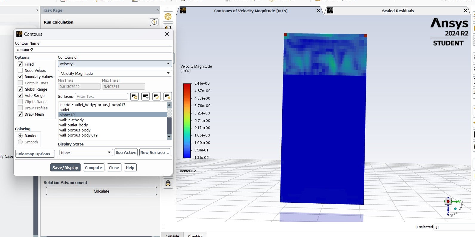
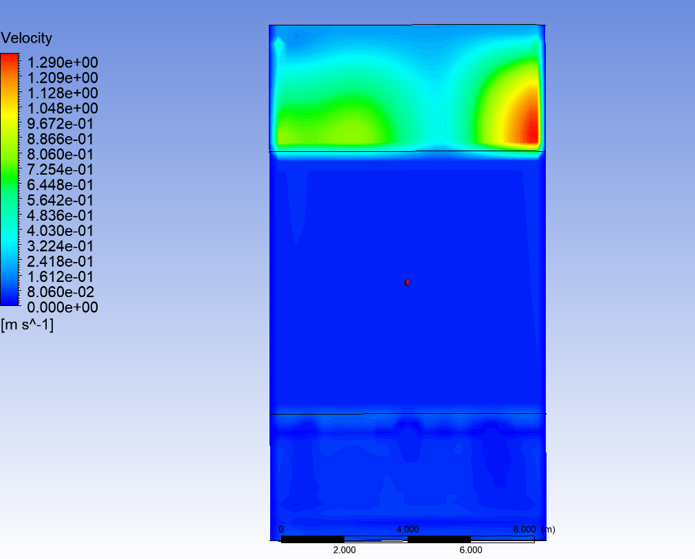
SubscriberThank you for your answer, i’m sorry if this is a strange question but im not so practical in Fluent. I send you the photo of my contour.. In practice i have an input velocity, plus a gravity term that should help the flow (im plotting velocity in all domain) . In output pressure is fixed at 0. It feels strange to me that velocity is blocked where porous media start and as a consequence also the temperature profile (flow enters at 1300 K) falls to zero immediately after the porous interior inlet
-
August 6, 2024 at 8:50 am
Rob
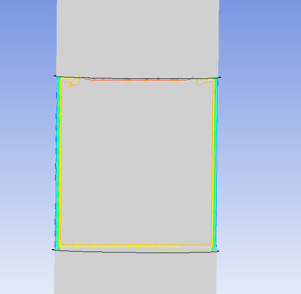
Forum ModeratorThat looks more of a problem with the mesh/result than a real value. Please replot in Fluent and do so with node values off & post that image.
-
August 6, 2024 at 11:00 am
-
August 6, 2024 at 12:47 pm
Rob
Forum ModeratorYes, that's correct. Why are you getting an odd velocity value in just two cells? How is the boundary set?
-
August 6, 2024 at 1:44 pm
chrivero
SubscriberI fixed the velocity in the inlet zone (above) like velocity magnitude (normal to boundary) and the inlet Temperature, and the pressure at the outlet (as 0 Pa)
-
August 6, 2024 at 1:49 pm
Rob
Forum ModeratorThat still shouldn't give the single cell spike in value. I assume you mean you used a velocity inlet?
-
August 6, 2024 at 2:55 pm
chrivero
Subscriberyeah exactly
-
August 6, 2024 at 3:02 pm
Rob
Forum ModeratorHow well converged is the solution?
-
August 7, 2024 at 9:04 am
chrivero
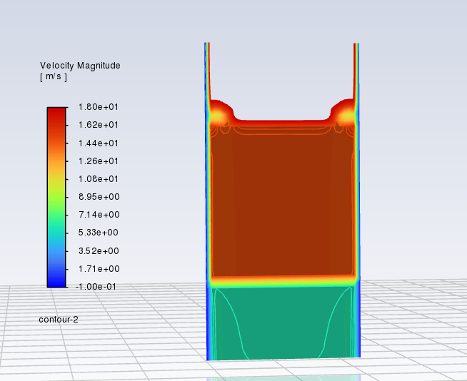
Subscribersorry if i opened the new thread, for some reason i was not able to see my old post. Yeah looking at the resisuals the solution is well converged, i think there's something physical that is blocking.
For instance after trying several time this is what i can see plotting the velocity in the fluid part of porous body
-
August 7, 2024 at 9:16 am
Rob
Forum ModeratorHow does the mass flux balance look? Turn off auto range on the contour plot, turn on filled and expand the scale (range) by a small amount at each end (so 0 to 5ms would be -0.01 to 5.01m/s). The porous region won't slow/accelerate the flow (read the theory) but equally shouldn't stop it unless the flow can bypass the porous zone.
-
August 7, 2024 at 9:44 am
chrivero
Subscriber -
August 7, 2024 at 10:03 am
Rob
Forum ModeratorThe sign on interior faces isn't generally useful as it's linked to the face normal: that's not far off random on an interior and may not even be the same over the whole surface! If you switched on the "physical velocity" options turn them off. They're supposed to mimic flow acceleration but never seem to give a good result.
Did you use standard or hybrid initialisation?
-
August 7, 2024 at 11:58 am
chrivero
Subscriberyeah i used superficial velocity but i also tried with physical only to check if the results were different. I use standard initialisation and then i patch the initial temperature of the porous solid
-
August 7, 2024 at 1:24 pm
Rob
Forum ModeratorThat sounds right. To confirm, you patched the solid? Solid porosity is < 1 ? Model is transient?
-
August 7, 2024 at 1:45 pm
chrivero
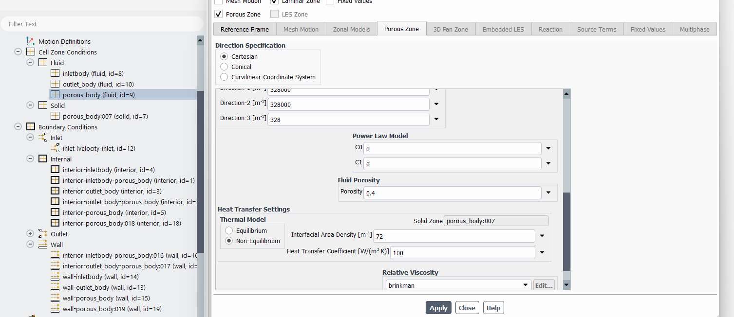
SubscriberYeah i patched the solid temperature, my porosity is 0.4, i put data for viscous and inertial resistance and before entering a UDF for heat transfer coefficient i fixed a constant value. The model is transient
-
August 7, 2024 at 1:55 pm
Rob
Forum ModeratorAnd it's failing with a fixed HTC?
-
August 7, 2024 at 3:20 pm
chrivero
Subscribersadly yes.. after a certain time all the inlet zone has full reached the inlet Temperature and at the beginning of porous is still ambient temperature
-
August 7, 2024 at 3:36 pm
Rob
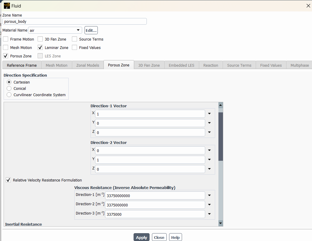
Forum ModeratorCan you post screen shots of the porous zone settings, along with the equivalent fluid zone? I'm not aware of any significant issues with what you're trying so it's a case of looking to see what's set. To comply with Forum rules I can't download any files, so images only.
-
August 7, 2024 at 4:06 pm
-
August 7, 2024 at 4:12 pm
Rob
Forum ModeratorTurn off laminar zone. Also drop the HTC and see if that helps.
-
August 7, 2024 at 10:51 pm
chrivero
SubscriberI turn off laminar zone and now it works! Thank you so much really!
-
- You must be logged in to reply to this topic.


-
2979
-
970
-
857
-
750
-
599

© 2025 Copyright ANSYS, Inc. All rights reserved.

