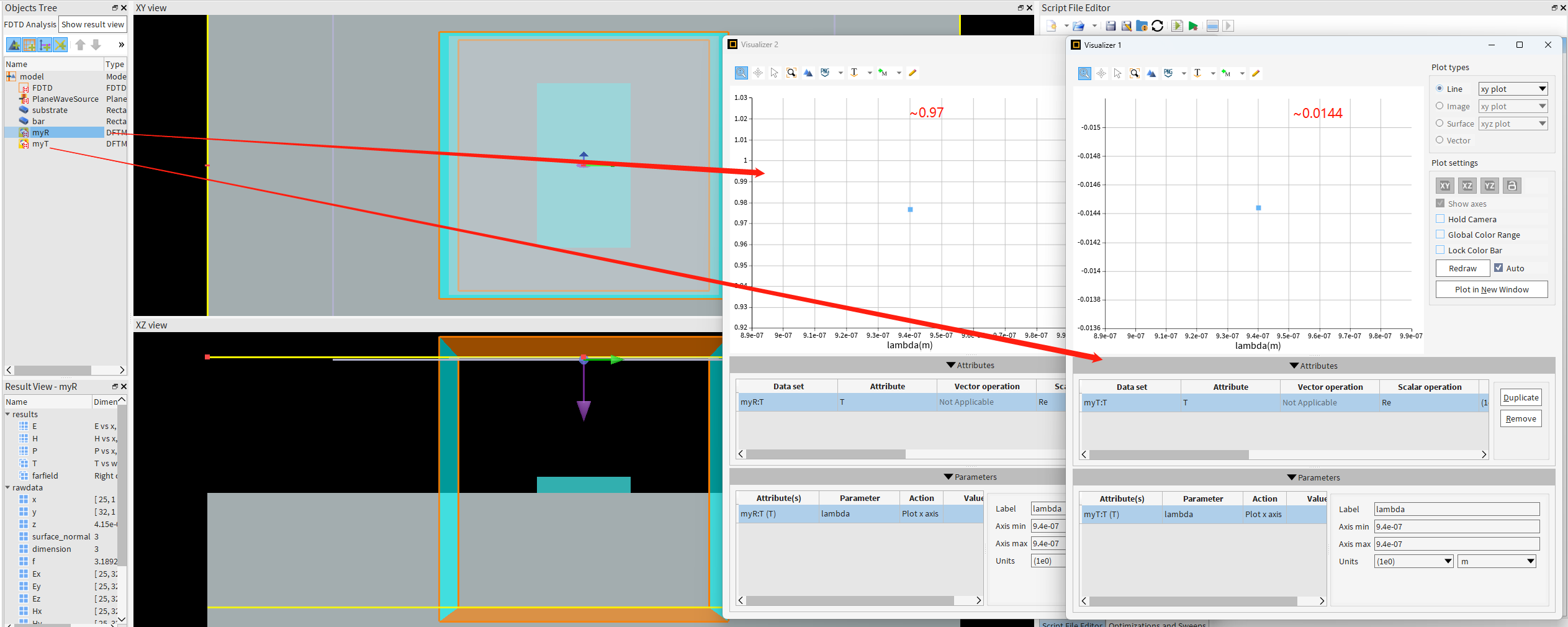
TAGGED: metamaterial, monitor
-
-
December 12, 2024 at 5:58 amxuanlunhuang20Subscriber
Hi, I’m simulating a 2d polarizer and have problem on recording the E field. I find that the field is not reflected in the movie even for a structure with high reflection. Could you help on this problem? What’s the correct setting for the movie monitor so that I can record the reflecting phenomenon?
Specifically, I use a silicon on glass meta-atom (its height is 500nm, x width is 160nm, y width is 280nm, index is 3.7) to simulate, which has a high transmission (~94.6%) for x-polarized light and a high reflection (~98%) for y-polarized light. I set the planewave source (940nm) to y polarization and want to record the movie of the E field being reflected back. I set two movie monitors, one is x-z direction (2D Y-normal) and another is y-z direction (2D X-normal).
But in the movies (for both the two monitors), the E field transmits through the structure and there is no light being reflected back. The following are the third second and sixth second of the movie. We can see that unlike the movies in the online example “Microwire polarizer”, in this movie, there is no field being reflected back. How can I get the movies like those in the "Microwire polarizer" example?
-
December 12, 2024 at 6:04 amxuanlunhuang20Subscriberperiod is 428nm
-
December 14, 2024 at 12:26 amAmrita PatiAnsys Employee
-
December 14, 2024 at 6:52 amxuanlunhuang20Subscriber
Hi Amrita,
I used the s-parameter group to record the reflection and transmission in the same simulation. The reflection is 97.5% and the transmission is 1.4%. This is the screenshot.
I also set a seperate 2D-z normal monitor "myR" above the source in the simulation, to serve as a verification, whose recorded value is 97.6%.
The physcial quantity I'm recording is Electric field intensity.
I also set a 2D Y normal time monitor to record the field, the following is the screenshot at two time, where we can see the field transmits through the structure.
-
-
December 18, 2024 at 10:27 pmAmrita PatiAnsys Employee
Hi Xuan,
I apologize for the delay in getting back to you, I sometimes don't receive updates when users reply.
I wouldn't expect this to happen. This might be a bug, but I wasn't able to reprduce the issue. Would you be able to convert the .mp4 to .gif and send it here?
Regards,
Amrita-
December 19, 2024 at 4:05 amxuanlunhuang20Subscriber
Hi Amrita,
Thanks for your reply. Here are the .gifs of the xz_movie monitor and yz_movie monitor:
xz:
yz:
I also upload the FDTD simulation file on dropbox. If it's convenient for you, you could download it to help check where the problem is. Thanks.
-
-
December 23, 2024 at 9:28 pmKirillAnsys Employee
Dear Subscriber,
According to the Guidelines for Posting on Ansys Learning Forum, we cannot download your files.
I attempted to reproduce your issue but was unsuccessful.
- What is the refractive index of the substrate?
- Do you get the same transmission and reflection results using only field monitors?
Best regards,
Kirill-
December 24, 2024 at 3:29 amxuanlunhuang20Subscriber
Hi Kirill,
I use the "SiO2 (Glass) - Palik" material for the substrate. For 940nm, it's about n=1.45.
As I mentioned in the reply to Amrita, I use the "s_params" group to record the reflection, it's ~97%. I also set my own moniter "myR" in the same simulation to double check, it's ~97%.
Following your suggestion, I redo the simulation with only the source, transmission monitor and reflection monitor. The result is the same.
-
December 24, 2024 at 3:47 amxuanlunhuang20Subscriber
I copy all my simulation details here. Could you copy and reproduce the simulation?
The screenshot of the simulation:
FDTD settings are: simulation time 10000fs, mesh 4, conformal 0, Bloch boundary in x and y, PML in z, PML use stretched PML steep angle, layer is auto (12).
Materials I use are: index=3.7 for "bar", "SiO2 (Glass) -Palik" for "substrate"
The variables of the model:
The script to change the dimensions of all the structure:
Lmax = 7e-6;
sourceoffset = 0.075e-6;
n1 = 1;
n2 = 1;
## set simulation region
select("FDTD");
set("x",0);set("y",0);
set("x span",period);
set("y span",period);
set("z max",0.5*Lmax/n2+height+sourceoffset*2);
set("z min",-0.5*Lmax/n1);
## set source
select("PlaneWaveSource");
set("x",0);set("y",0);
set("x span",period*3);
set("y span",period*3);
set("z",0.5*Lmax/n2+height+sourceoffset);
## set bar
select("bar");
set("x",0);set("y",0);
set("x span",wx);
set("y span",wy);
set("z max",height);
set("z min",0);
## set substrate
select("substrate");
set("x",0);set("y",0);
set("x span",period*3);
set("y span",period*3);
set("z max",0);
set("z min",-3*Lmax/n1);
# set myR
select("myR");
set("x",0);set("y",0);
set("x span",3*period);
set("y span",3*period);
set("z",0.5*Lmax/n2+height+sourceoffset*2);
# set myT
select("myT");
set("x",0);set("y",0);
set("x span",3*period);
set("y span",3*period);
set("z",-0.5*Lmax/n1);
# set xz-field
select("xz_field");
set("x",0);set("y",0);
set("x span",period);
set("z max",0.5*Lmax/n2+height+sourceoffset*2);
set("z min",-0.5*Lmax/n1);
# set xz-time
select("xz_time");
set("x",0);set("y",0);
set("x span",period);
set("z max",0.5*Lmax/n2+height+sourceoffset*2);
set("z min",-0.5*Lmax/n1);
-
December 27, 2024 at 7:12 pmAmrita PatiAnsys Employee
Hi Xuan,
Thanks for sharing the code! I did try to reproduce the issue but some of the input parameters like height, period etc. are missing. I used random values and in my case most of the light is transmitted, which I can see in the movie monitor. Would you be able to share the values of the missing input parameters so that I can recreate the exact simulation. Also, which release of Lumerical are you using?
Regards,
Amrita-
December 29, 2024 at 12:31 pmxuanlunhuang20Subscriber
Hi Amrita,
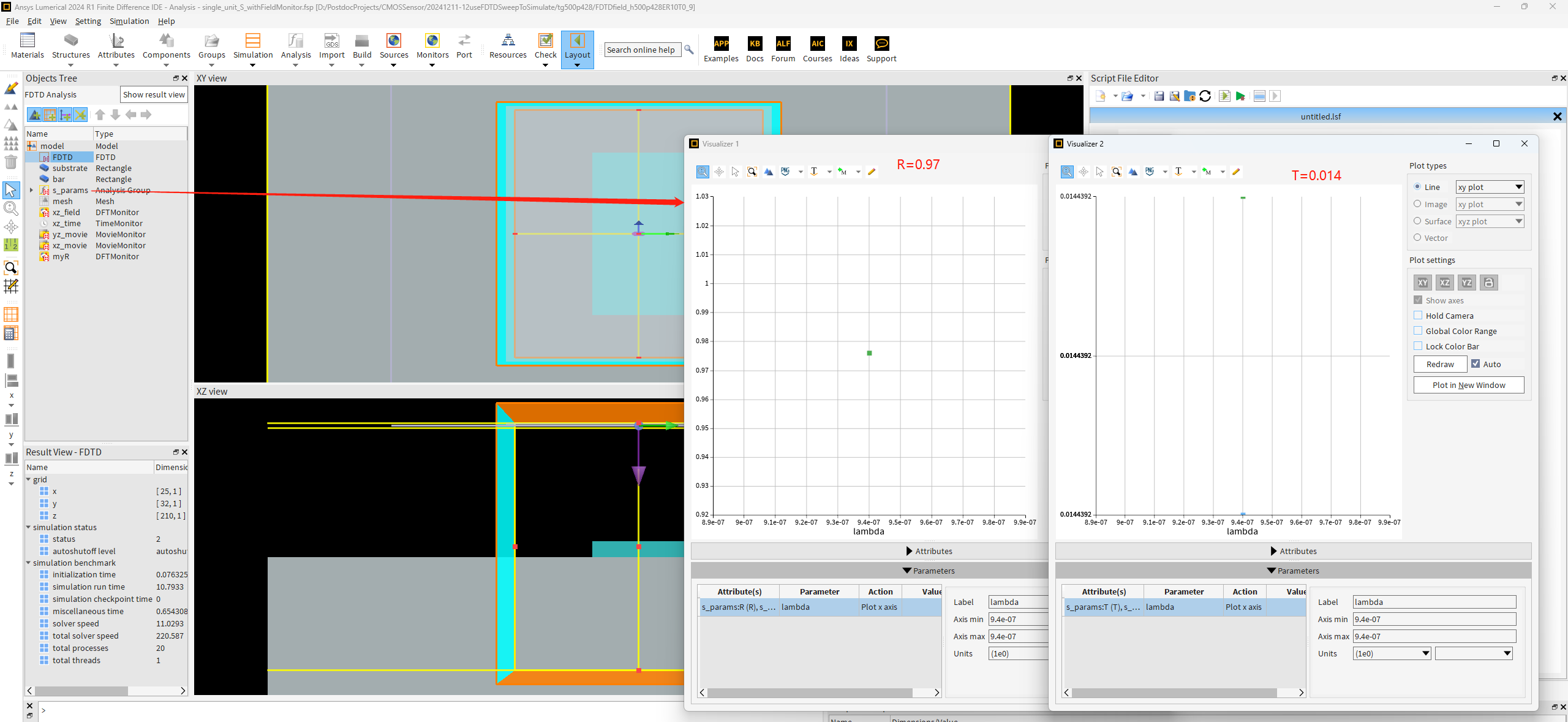
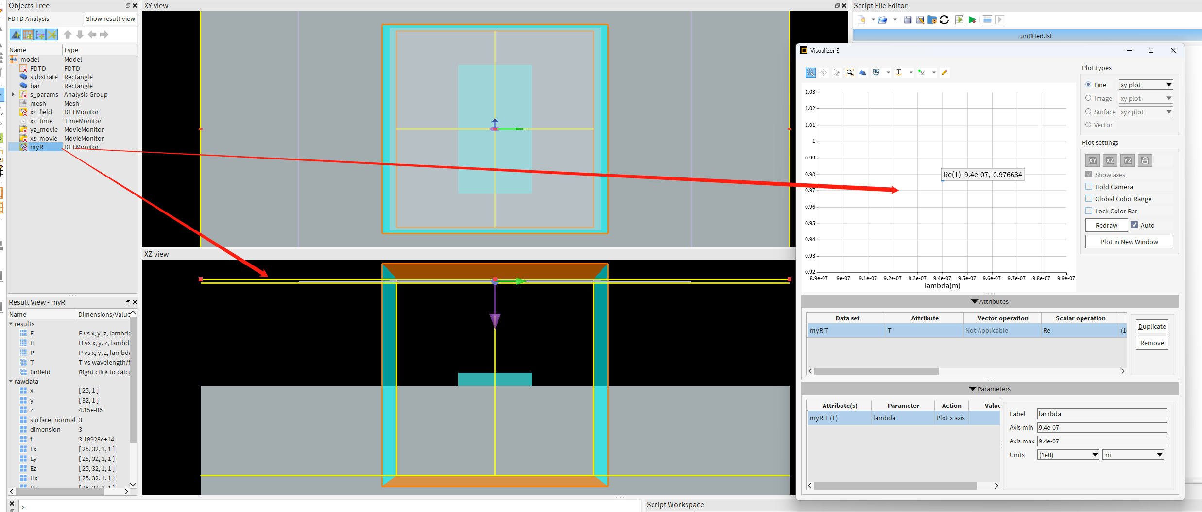
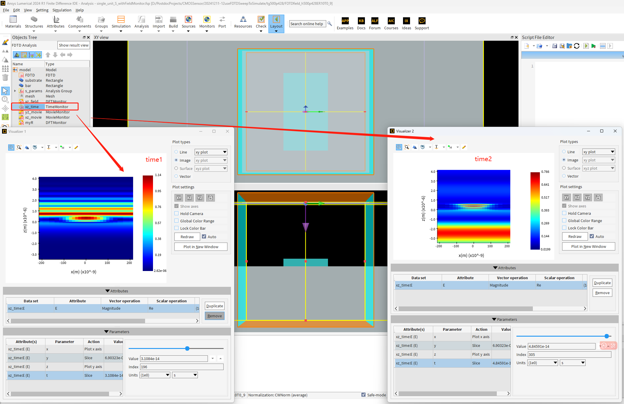
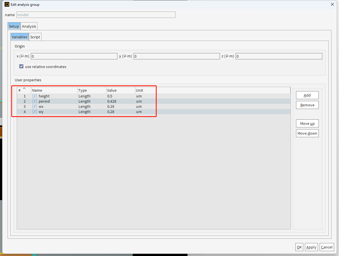
Thanks for your help. I have shown all the parameters in the previous replies (e.g. height is 500nm, period is 428nm). The versioin I use is 2024 R2.1 (or 2024 R1, the same problem happens in these two versions).
But for your convenience, I wrote a script and you could copy it directly to the model setup script and reproduce the simulation.
The following is the script (The reply window looks werid, cannot show all the script, please use this updated code):
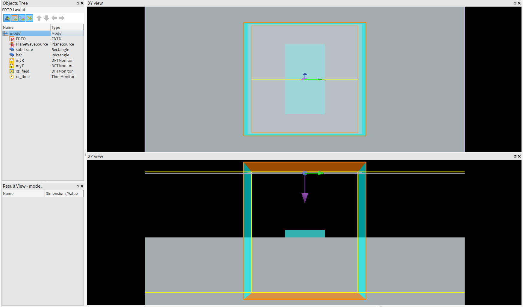
deleteall;height = 0.5e-6;period = 0.428e-6;wx = 0.16e-6;wy = 0.28e-6;Lmax = 7e-6;sourceoffset = 0.150e-6;n1 = 1;n2 = 1;
## set simulation region
addfdtd;set("dimension","3D");set("simulation time",10000e-15);set("index",1);set("mesh accuracy",4);set("mesh refinement","conformal variant 0");set("x min bc","Bloch");
set("y min bc","Bloch");set("bloch units","SI");set("pml type",2);set("pml profile",3);set("auto scale pml parameters",0);set("snap pec to yee cell boundary",0);
set("x",0);set("y",0);set("x span",period);set("y span",period);set("z max",0.5*Lmax/n2+height+sourceoffset*2);set("z min",-0.5*Lmax/n1);
## set source
addplane;set("name","PlaneWaveSource");set("direction","Backward");set("polarization angle",90);set("wavelength start",940e-9);
set("wavelength stop",940e-9);set("x",0);set("y",0);set("x span",period*3);set("y span",period*3);set("z",0.5*Lmax/n2+height+sourceoffset);
## set substrate
addrect;set("name","substrate");set("x",0);set("y",0);set("x span",period*3);set("y span",period*3);set("z max",0);set("z min",-3*Lmax/n1);
set("material","
## set bar
addrect;set("name","bar");set("x",0);set("y",0);set("x span",wx);set("y span",wy);set("z max",height);set("z min",0);set("material","
# set myR
addpower;set("name","myR");set("monitor type","2D Z-normal");set("x",0);set("y",0);set("x span",3*period);set("y span",3*period);set("z",0.5*Lmax/n2+height+sourceoffset*2);
# set myT
addpower;set("name","myT");set("monitor type","2D Z-normal");set("x",0);set("y",0);set("x span",3*period);set("y span",3*period);set("z",-0.5*Lmax/n1);
# set xz-field
addprofile;set("name","xz_field");set("monitor type","2D Y-normal");set("x",0);set("y",0);set("x span",period);set("z max",0.5*Lmax/n2+height+sourceoffset*2);set("z min",-0.5*Lmax/n1);
# set xz-time
addtime;set("name","xz_time");set("monitor type","2D Y-normal");set("stop method","Choose Stop Time");set("start time",0);set("stop time",50e-15);set("x",0);set("y",0);set("x span",period);set("z max",0.5*Lmax/n2+height+sourceoffset*2);set("z min",-0.5*Lmax/n1);
# set xz-movie
addmovie;set("name","xz_movie");set("monitor type","2D Y-normal");set("x",0);set("y",0);set("x span",period);set("z max",0.5*Lmax/n2+height+sourceoffset*2);set("z min",-0.5*Lmax/n1);
-
December 31, 2024 at 6:18 amxuanlunhuang20Subscriber
...
-
December 31, 2024 at 6:20 amxuanlunhuang20Subscriber
...
-
-
- You must be logged in to reply to this topic.
- Difference between answers in version 2024 and 2017 lumerical mode solution
- Errors Running Ring Modulator Example on Cluster
- Import material .txt file with script
- Trapezoidal ring
- Help for qINTERCONNECT
- Absorption cross-section of AuNR excited by prism-based TIR
- Issues with getting result from interconnent analysis script
- Topology Optimization Error
- How to measure transmission coefficients on a given plane .
- Edge Coupler EME Example Issue
-
1617
-
613
-
599
-
591
-
366
© 2025 Copyright ANSYS, Inc. All rights reserved.