Hi Everyone,
I am having some problems in simulating simple parallel plate waveguide in HFSS. I will appreciate if you can suggest some solutions.
I tried making the parallel plate waveguide (whose cut off frequency is 10 GHz) in two ways:-
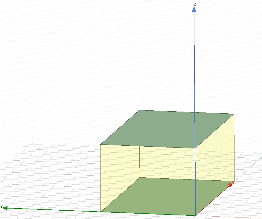
1) I choose a box and choose dimensions are such that the cut off frequency of waveguide is 10GHz. I assigned perfect electric boundary to both top and bottom plate and PML( Perfectly marched layer) boundary to other two sides, because I read that it is used to emulate a perfect absorber. On the other two sides, I assigned wave port( tried with and without defining the integration line)
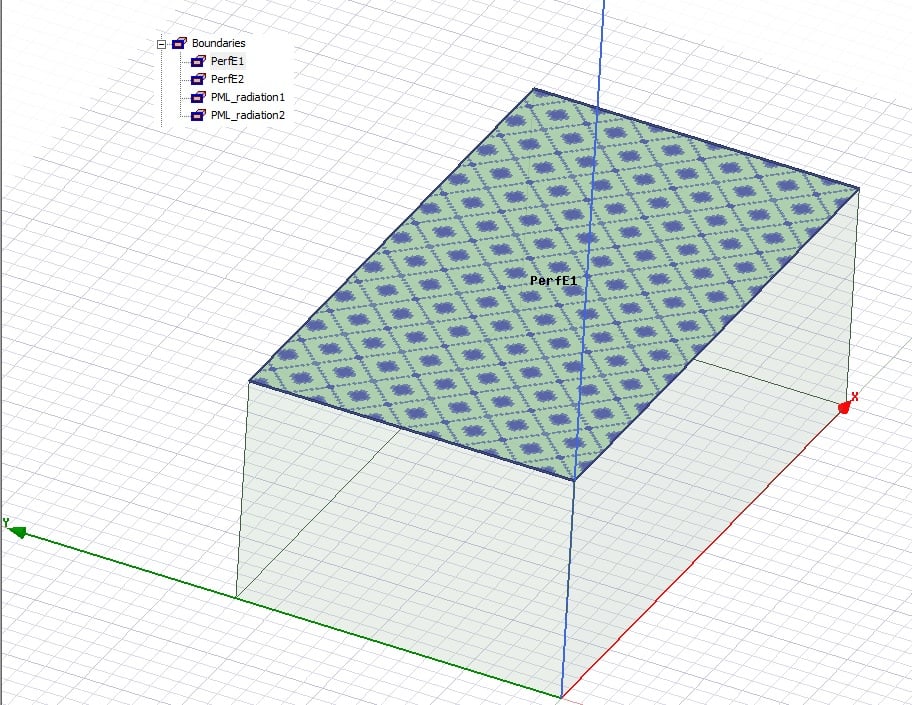
2) Second, case is similar to the first one but instead of assigning Perfect Electric boundaries to top and bottom sides of the box, I built small layer of PEC on top of them (the thickness is very small)
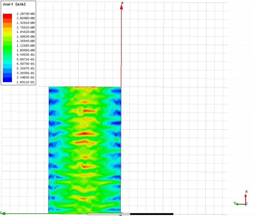
Problem:- After I run the simulation, I don't obtain the surface currents on the bottom plate as I expect.They should be constant and not sinusoidal.
My Preception : The structure is correct, the problem has something to do with the excitation.
Actually, I have worked with only lumped ports before, this is the first time I am dealing with the wave port.
I am attaching the magnitude plot of surface current and Complex magnitude plot of surface current.

I will appreciate if you could help me with this.
Warm Regards
Akshaj Arora


