TAGGED: pressure-outlet, reversed-flow
-
-
July 15, 2021 at 5:18 am
Danielgkh
SubscriberHi,
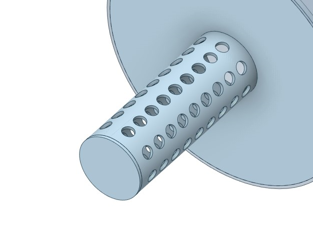
I would like to ask, if my pressure outlet consists of lots of holes on a cylindrical wall, how should I extend the domain to prevent reverse flow?
The geometry looks like this.
July 15, 2021 at 11:02 amRob
Forum ModeratorReverse flow isn't a problem in itself. It's only a problem if it alters the result. As we don't know what you're modelling it's hard to advise. Adding "spikes" to the model isn't the right way to solve this though, the drum is a much better solution.
July 15, 2021 at 12:17 pmDanielgkh
Subscriber
I am modelling an exhaust gas muffler. So basically, after passing through a few chambers, the air is supposed to leave through these pores into the enclosed cavity of a condensing heat exchanger. For this case, I had set a constant mass flow rate and 0 Pa pressure outlet. Gravitational acceleration is pointing downwards. The air is coming in at around 300C and my backflow temperature is 100C, as this is the max operating tempertaure of the heat exchanger.
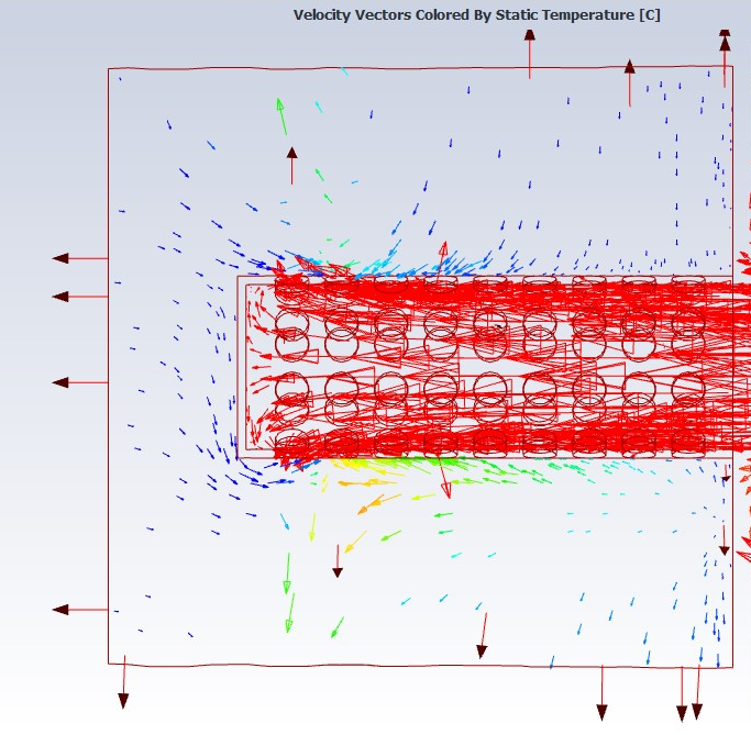 The thing is I dont really know if this might be the actual flow, but I feel like, it should not be. Does it help with the situation if I increase my backflow temperature?
If I would like to proceed with this "drum" domian, is it appropriate for me to set the outlet at these 2 faces? Or just one face, either at the flat face or the curved face?
I had also ran a simulation with the "spikes" and it shows a better result at preventing reverse flow, which of course the air has nowhere else to go other than the narrow "spikes".
Thank you.
July 15, 2021 at 12:58 pmRob
Forum ModeratorIf the muffler is venting into space then you may want a slightly bigger outer domain. What you are aiming for is to replicate reality. The tubes will reduce backflow, but will also add a pressure loss to the flow: does this then alter anything upstream?
Put a plane through at a position that is central to a row of holes, I think that'll help explain what's going on.
July 15, 2021 at 2:04 pmDanielgkh
Subscriber
so I did as you said at different row of holes and I got these 2 vectors plot.

 What I can see is that even though the reverse flow doesn't actually affect my outflow of gas from the pipe, they form some weird pathway, for example at the bottom corner and the bottom part of the pipe.
So can I treat this reverse flow not as a problem, but more as a replication of reality? Although I still don't really understand how it happens. The faces of pressure outlet has a lower pressure than the fluid domian, so how can fluid still flows in?July 15, 2021 at 3:12 pmRob
Forum ModeratorThat looks fine. If you'd added (and labelled) interior faces in the holes you'd be able to report the mass flow through each hole or row of holes too.
Re the back flow. You have jets of fluid coming from the muffler. These entrain the surrounding fluid and both expand and slow down. Where does the entrained fluid come from? Check the mass balance between what goes into the exhaust system and what leaves the outlet domain, they should be the same.
July 16, 2021 at 5:17 amDanielgkh
SubscriberHi I see, thanks for the advice. I will make the changes and simulate it again.
Regarding the back flow, the fluid is coming from outside the fluid domain, as shown in the following pathline diagrams, particle released from outlet.

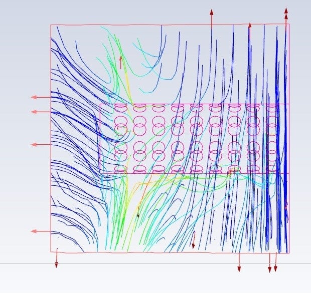
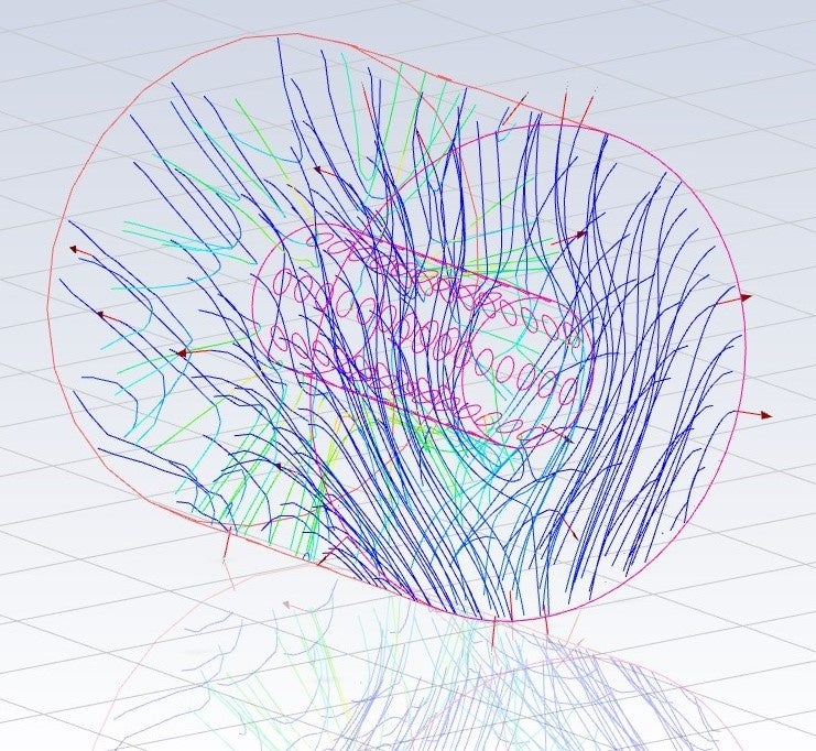 And here is the mass flow rate report. Around 40% of mass has gone missing.
 So, is this result acceptable?
Will changing the BC from pressure outlet to pressure farfield improve the situation? As I am simulating compressible flow, outflow BC is not appropriate, according to user guide.
The reason backflow is not really favourable/realistic is because the closed cavity of condensing heat exchanger actually has a slightly higher pressure (~5 mbar) than to say, the open space, where the fluid is supposed to be exhausted. So there is almost no way for fluid to reenter the closed cavity from open space and into the outlet pipe in my model. In my case, I had set the gauge pressure at pressure outlet to be 0 Pa just so that the fluid can flow properly. Operating pressure is at 1 atm.
July 16, 2021 at 1:07 pmRob
Forum ModeratorIn which case sort the convergence out first as that may be why the back flow is occurring. Assuming the pressure loss is fairly low use the incompressible ideal gas as that'll help with solver stability.
July 17, 2021 at 5:20 pmDanielgkh
Subscriber
so I had re-run the simulation for much longer and here are what I got.

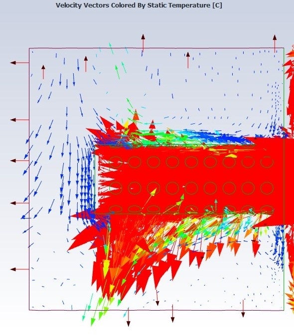

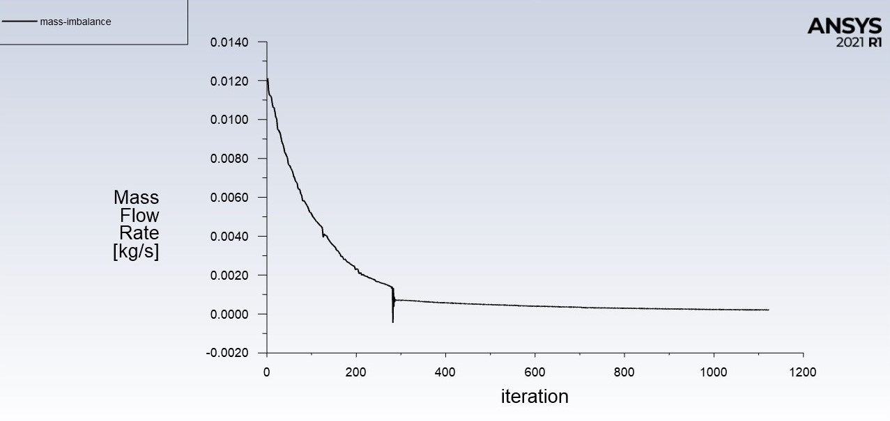
 From the vector plots, you can see that air is flowing into the fluid domain from mostly the top part and exiting through the bottom part which I think, mimics the reality quite accurately. However, although the mass imbalance has basically flat out, my residual plot has problem converging. Incompressible ideal gas is not suitable for my simulation as there is also heat transfer involved, with fluid temperature ranging from 80 C to 450 C.
In this case, can I still take this result as being accurate, and the problem with converging is basically caused by the reverse flow which doesn't really interfere with my actual fluid flow?
(Just for better understanding, here is what the model will looks like when installed, https://sermeta.com/wp-content/uploads/sites/2/2018/08/Condensation-ENG3.png)
July 19, 2021 at 10:32 amRob
Forum ModeratorIncompressible ideal gas is designed for high temperature change systems with minimal pressure loss: ie it changes density with temperature but not pressure. For an exhaust system I'd expect it to be perfect.
Your results will be affected by the backflow, but also you may be seeing some transients due to jetting and jet interaction. If you plot velocity contours over a few hundred iterations you should be able to see this. Depending on what data you need/want from the model it's probably OK to use.
July 19, 2021 at 11:53 amDanielgkh
Subscriber
Thanks again for your advice, I really do appreciate it.
The data I want from this steady-state simulation with constant mass flow rate are temperature, pressure, velocity and sound pressure level using broadband noise source model(1st part). Followed by this, I will run a transient simulation with varying mass flow rate to get the spectral analysis of sound pressure level(2nd part).
The only difference between BC for steady and transient simulation is the mass flow rate(and of course the solver control). Part of the reason I chose compressible ideal gas law is because I do not want to have too much difference between my steady and transient simulation. I am not too sure, how big the difference between both of these simulation will be if I choose different properties for density, on top of varying mass flow rate. And also, from the current simulation the air speed inside the muffler can reach up to 0.25 Mach, so it is risky.
For understanding, I had ran a brief transient simulation with constant mass flow rate and to my surprise, the residual converged properly. I never thought about running this simulation because for the 1st part, I just need a rough understanding of the property changes and also, it provide an initial value for my transient simulation in 2nd part. I did also notice the jetting you mentioned.
So now, I am having a dilemma of which setting to choose.
Steady(the norm) or Transient(converged)? Or pseudo transient? Compressible or incompressible?
Otherwise I will just use the result from the current simulation as it is.
July 19, 2021 at 1:22 pmRob
Forum ModeratorWith 0.25M you're borderline compressible so it's a difficult one to judge without reviewing the results (I'm not going to as we're limited in what we can say and how much time we spend on here). Given you want to look at acoustics, check what inputs are required there.
Transient often converges better because you actually model (if you do it right) the fluctuations in flow. The reason we don't model everything as transient is down to time: you need to run at least one residence time (ideally a few) to flush out the initial conditions and that may take 10s of thousands of iterations against 500-1500 for a steady case. I often run steady then move to transient with a nearly converged solution, this does reduce the number of residence times before I can take data: use point monitors to report the transient data and look for a steady pattern.
July 20, 2021 at 8:26 pmDanielgkh
Subscriber
I think I know what to do already. Thanks so much for your help.
Viewing 12 reply threads- The topic ‘Pressure Outlet of Holes on Cylindrical Wall’ is closed to new replies.
Ansys Innovation SpaceTrending discussions- Non-Intersected faces found for matching interface periodic-walls
- Unburnt Hydrocarbons contour in ANSYS FORTE for sector mesh
- Fluent fails with Intel MPI protocol on 2 nodes
- Help: About the expression of turbulent viscosity in Realizable k-e model
- Cyclone (Stairmand) simulation using RSM
- error udf
- Mass Conservation Issue in Methane Pyrolysis Shock Tube Simulation
- Script Error
- Facing trouble regarding setting up boundary conditions for SOEC Modeling
- UDF, Fluent: Access count of iterations for “Steady Statistics”
Top Contributors-
1416
-
599
-
591
-
565
-
366
Top Rated Tags© 2025 Copyright ANSYS, Inc. All rights reserved.
Ansys does not support the usage of unauthorized Ansys software. Please visit www.ansys.com to obtain an official distribution.
-
The Ansys Learning Forum is a public forum. You are prohibited from providing (i) information that is confidential to You, your employer, or any third party, (ii) Personal Data or individually identifiable health information, (iii) any information that is U.S. Government Classified, Controlled Unclassified Information, International Traffic in Arms Regulators (ITAR) or Export Administration Regulators (EAR) controlled or otherwise have been determined by the United States Government or by a foreign government to require protection against unauthorized disclosure for reasons of national security, or (iv) topics or information restricted by the People's Republic of China data protection and privacy laws.

