-
-
July 24, 2024 at 7:39 pm
Shivaansh Adlakha
Subscriber1. I was trying to follow this tutorial- https://innovationspace.ansys.com/courses/courses/cfd-simulation-of-an-f1-in-schools-car-model-using-ansys-discovery/lessons/performing-your-first-cfd-simulation-on-an-f1-in-schools-car-model-using-ansys-discovery-lesson-3/
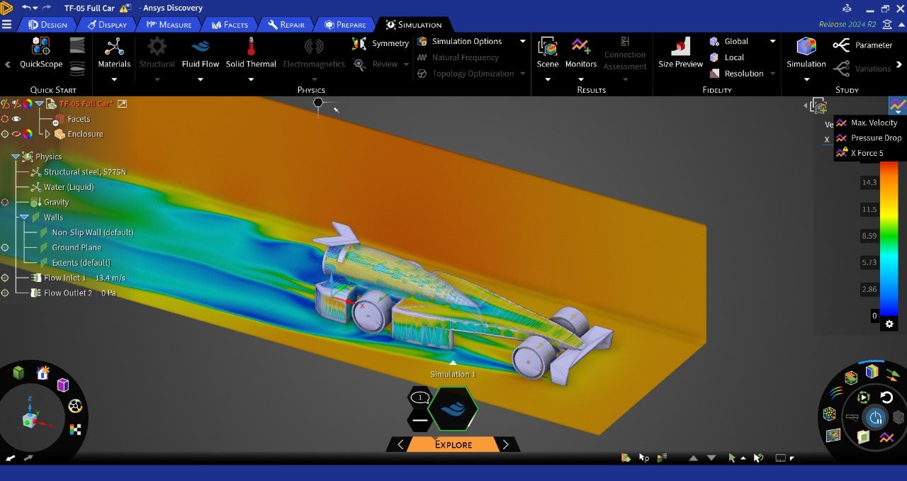
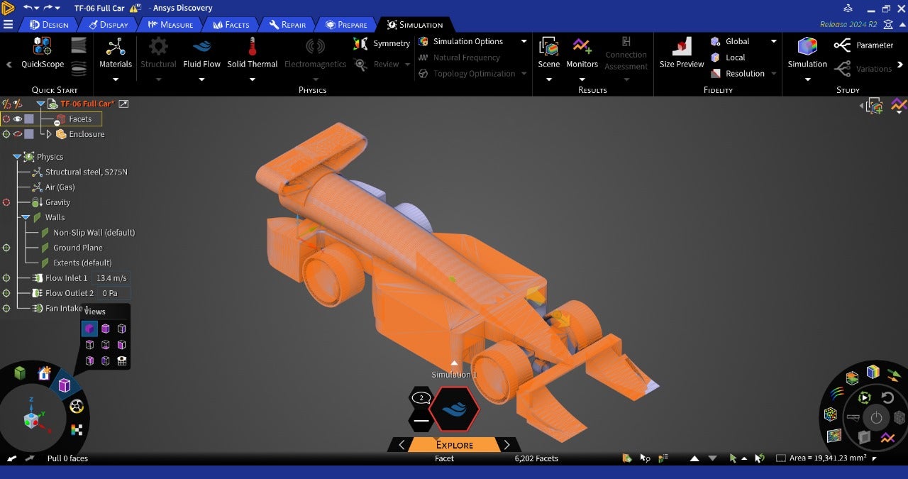
And at the stage where the force monitor needs to be put, it wasn’t letting me click the accept button (check mark) after giving all the conditions. Now, on research it appears that the faces might be selected instead of the body; which may be what’s causing the issue. I was selecting the body by triple clicking the car body because the selection through dragging the mouse wasn’t happening (as was done in the video). Possible fix for this?
-
July 25, 2024 at 5:11 am
-
July 27, 2024 at 6:35 pm
-
July 29, 2024 at 10:50 am
Devendra Badgujar
Forum ModeratorHi,
This is strange, can you share an image where the monitor is defined? Is it same for other sample models?
We do not have option to calculate drag coefficient directly, you can still calcutae it manually with an formula. But you can find the projected area as shown in this article: How to measure the projected area in Ansys Discovery - Ansys Knowledge
Regards,
Devendra
-
July 29, 2024 at 3:32 pm
Shivaansh Adlakha
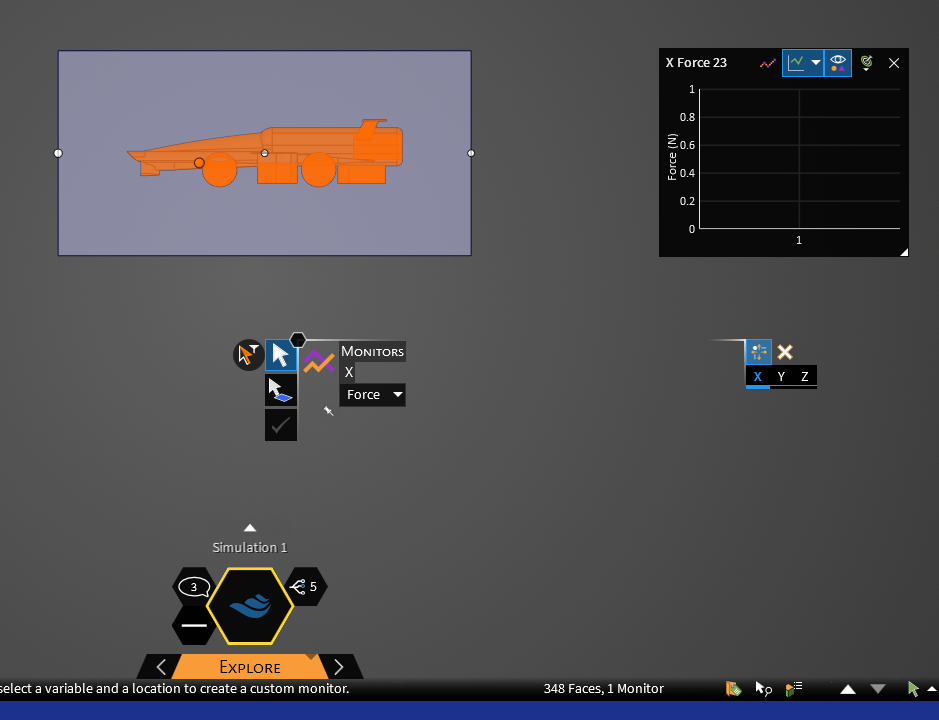
SubscriberThis is the error message after we selected the walls of the enclosure as the target instead of the body. When we were trying to select the body by triple clicking (it worked for the velocity monitor), it was not giving the check mark option for the force monitor.
Could the lack of output be because we chose the enclosure walls instead of the body? If yes what can be done now?
Also, for the drag coeffcient if I were to put the parameters in the formula would these be correct(Drag Force- Force I get from X axis force monitor?, Velocity- The flow inlet velocity? and density- density of air?)
-
July 30, 2024 at 3:17 pm
Devendra Badgujar
Forum ModeratorHello Shivaansh,
Make sure you select the faces from the enclosure. First go to Monitors>>Select the Force as result variable to monitor and then box select your geometry it will automatically select the car faces which were substacted from the enclosure during geometry preperation level.
Note: Hide your orginal car body.
Thanks,
Devendra
-
July 30, 2024 at 3:23 pm
Shivaansh Adlakha
SubscriberHow do I subtract the faces of the car from the enclosure? I think that’s what I haven’t been doing that’s causing the problem.
-
July 30, 2024 at 3:31 pm
Shivaansh Adlakha
SubscriberAlso, would this have affected my previous results with the Velocity Monitor?
-
July 31, 2024 at 9:55 am
Devendra Badgujar
Forum ModeratorHello Shivaansh,
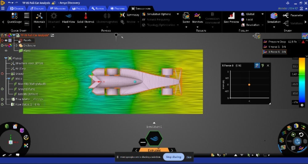
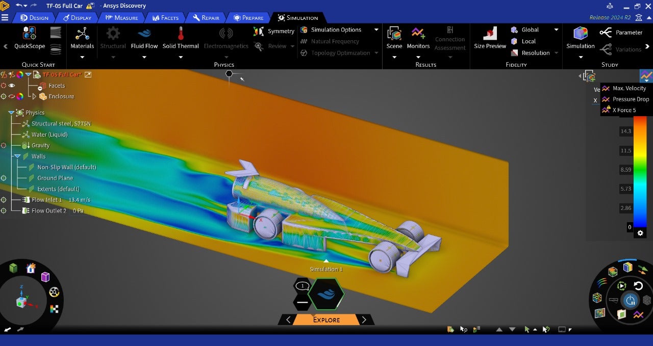
Can you please share an image of your full Discovery screen inclduing the Design and Physics tree. I want to see how the model is setup.
There are two ways:
- You can use Enclosure where the geometry will get automatically substracted from the domain.
- You can use Cutter bodies to automatically block the fluid flow without having to extract the overlapping bodies from the fluid.
Both options are fine, but the object selection would differ when defining monitors. If velocity monitor is not showing any warning, that means it is correct.
Regards,
Devendra
-
July 31, 2024 at 10:09 am
Devendra Badgujar
Forum Moderator -
July 31, 2024 at 12:18 pm
-
July 31, 2024 at 12:20 pm
Shivaansh Adlakha
SubscriberAs far as subtracting the geometry is concerned, I did create the enclosure through the Simulation tab>External Volume
-
July 31, 2024 at 1:14 pm
Devendra Badgujar
Forum ModeratorHello,
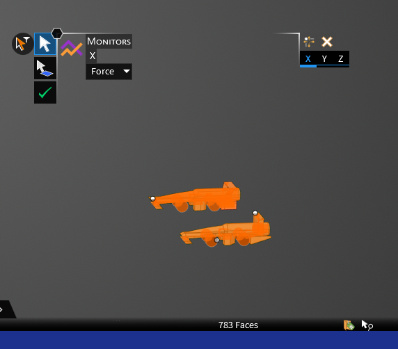
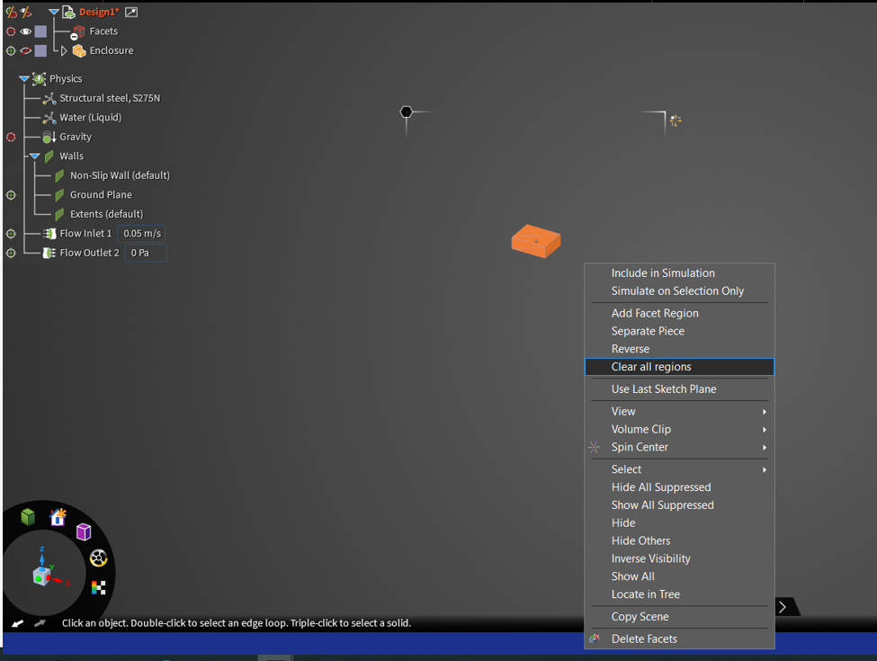
I got the problem, it looks like we have to first have to clear all regions from facet region to define the monitor on it. Select the car and clear all regions:
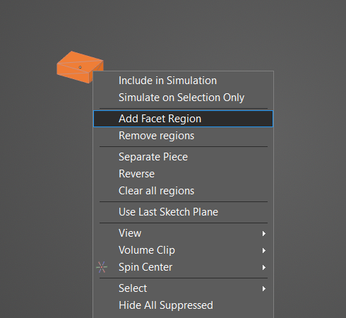
After this, select the car faceted body and do add facet region. Than go to monitors>force and select just car by clicking on it and that will allow you to define monitor correctly.
I hope this helps. Thank you!
-Devendra
-
July 31, 2024 at 4:57 pm
-
July 31, 2024 at 5:00 pm
-
July 31, 2024 at 5:31 pm
-
August 1, 2024 at 5:48 am
Devendra Badgujar
Forum ModeratorHello,
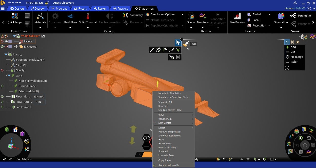
Selections with facteded body can sometimes be difficult as there are multiple facets. Select all does not give option to add as a facet region currently so only option is to box select and add the region to define simulation conditions.
I would recommend please use the Solid 3D CAD instead of facted body for simulations as its easy to setup and you cna make quick design changes to it. The geometry is avilable to download from the course.
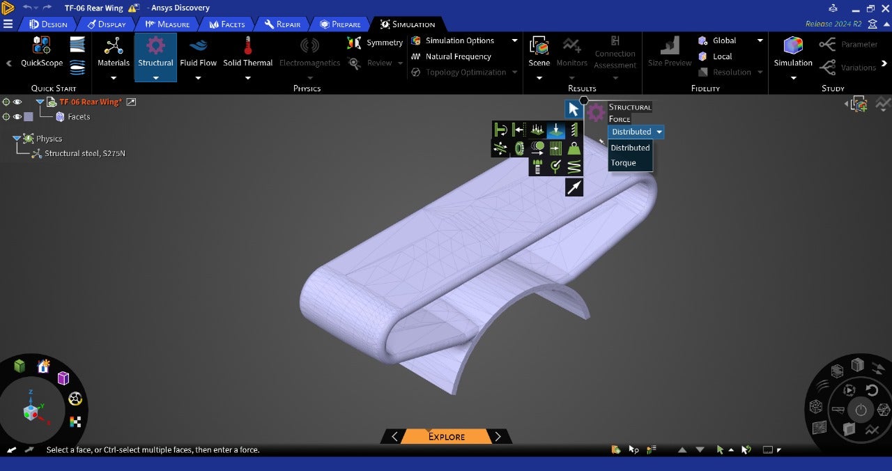
Similarly for the rear wing, you are not able to define force because the facets on which the conditions needs to be defined has not been added as facet region.
Thank you for your understanding!
Regards,
Devendra
-
August 1, 2024 at 8:14 am
Shivaansh Adlakha
SubscriberActually I needed to test this specific model for my F1 In Schools competition. Can I import it in another format to make it a solid 3D CAD body?
-
August 1, 2024 at 8:19 am
Devendra Badgujar
Forum ModeratorYou can convert the Facet to Solid by clciking on convert to solid. But instead doing that, you can directly get the same CAD as a solid from this Performing your first CFD Simulation on an F1 in Schools Car Model using Ansys Discovery - Lesson 3 - ANSYS Innovation Courses.
Regards,
Devendra
-
- You must be logged in to reply to this topic.


- Unable to attach geometry 2024 R2
- Getting Mesh Faces With Specified Normal Via SpaceClaim Scripting (V241)
- How to provide blade angles in bladegen.
- DXF file loaded incorrectly
- plugin error failed to import assembly from spaceclaim
- Overlapping contact face
- Thermoelectric Cooler Model
- Issue Seeing Explore
- Warning Plugin Error Geometry in Design Modeler
- SpaceClaim stops sharing topology

-
1416
-
599
-
591
-
565
-
366

© 2025 Copyright ANSYS, Inc. All rights reserved.

