-
-
July 24, 2024 at 8:29 am
d1227078662
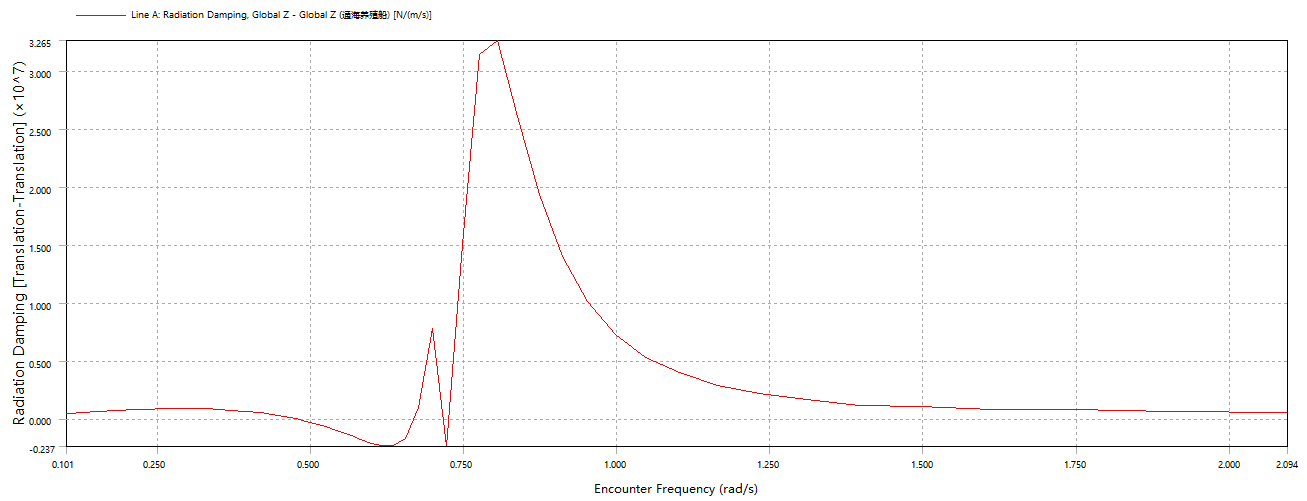
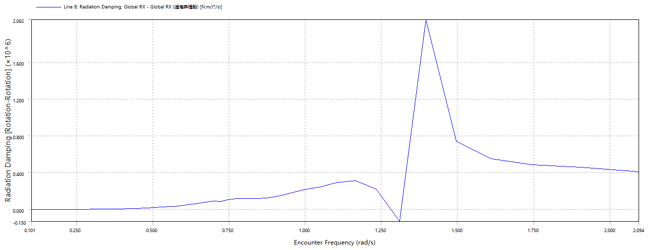
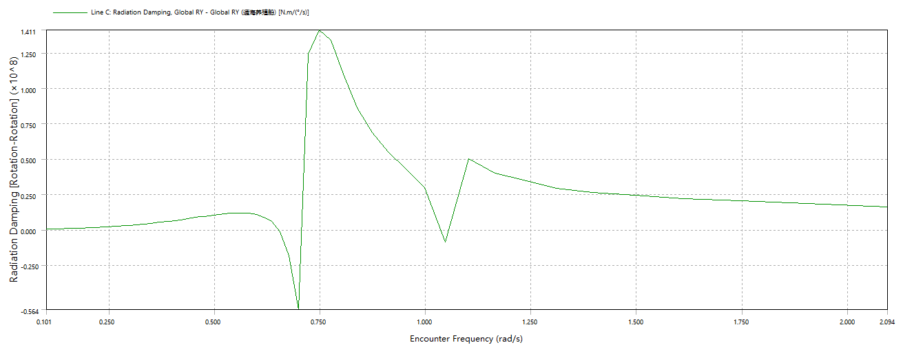
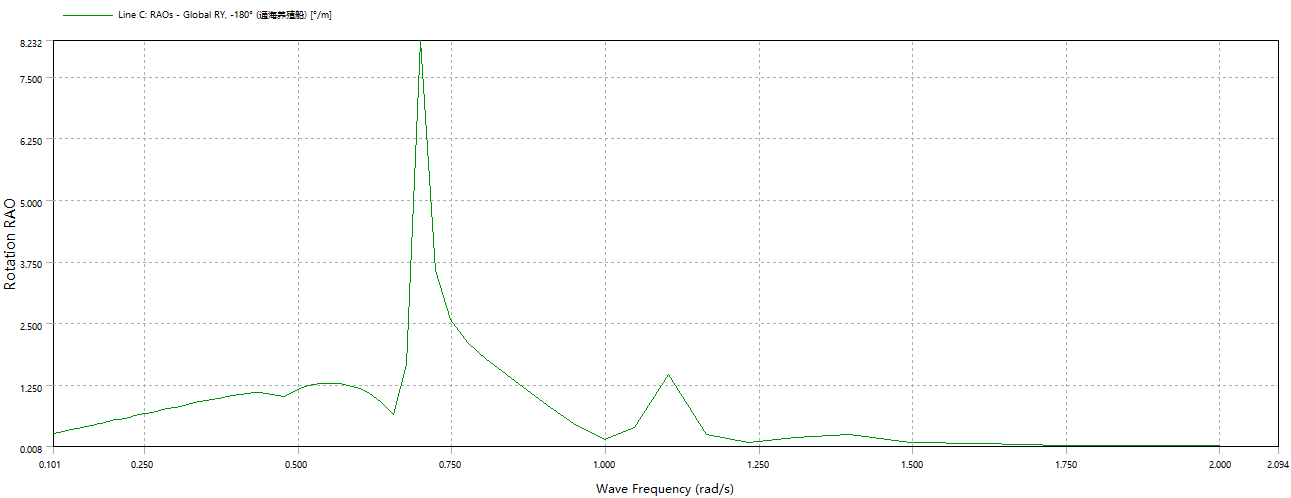
SubscriberThe ship that I want to calculate and analyze is quite special, it is a breeding ship converted from a bulk carrier, and the two breeding compartments of the ship have been opened on the side, which makes its two compartments communicated with the seawater, when I carry out the hydrodynamic calculation of the ship, I find that the ship has negative radiation damping in the three directions of Heave, Roll, and Pitch. The motion response at the corresponding frequencies is particularly sharp.I have used this option of Generate Internal Lid。The ship model and the corresponding calculation results are shown in Fig.
May I ask what should be the best way to approach this situation that I have encountered and thank you for your answer.
-
July 29, 2024 at 12:41 pm
CFD_Friend
Ansys EmployeeHi Cheng,
Which software tool are we talking about here?
-
July 30, 2024 at 1:13 pm
d1227078662
SubscriberThe software I use is Workbench AQWA.
-
-
July 31, 2024 at 1:38 pm
Mike Pettit
Ansys EmployeeHello,
That is an interesting case! A few questions:
- Please can you confirm the draft of the vessel?
- Are all of the openings submerged?
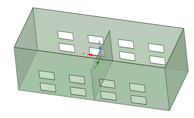
- If I understand your description and the images well, there is a partition running port-starboard across the middle of the vessel. Is this modelled with diffracting elements?Applying the Generate Internal Lid option is a good choice. I suspect the spiky radiation damping may be due to the interior surfaces, assuming that they are modelled with diffracting panels.
We would recommend that you give the vessel plates a thickness, and then detach the inside surfaces so that you can specify them as non-diffracting in the hydrodynamic analysis. I've set up a simplified model to check this:
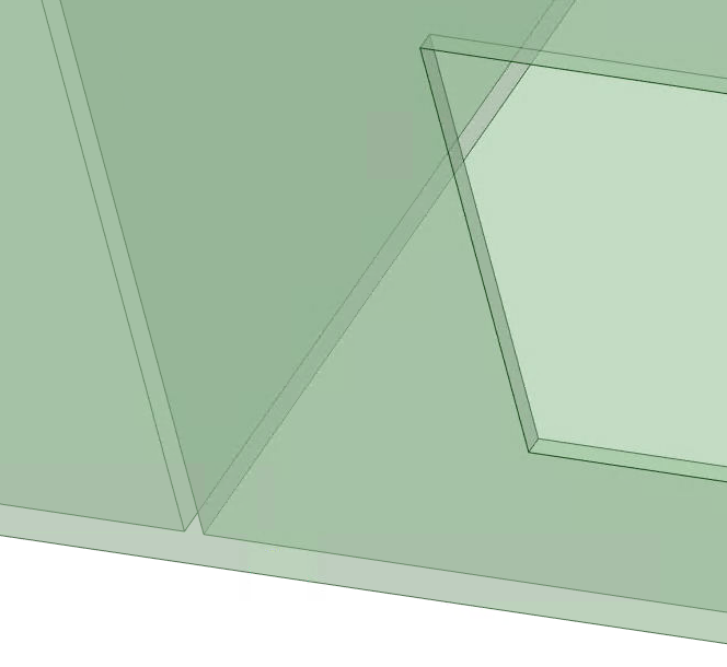
Zoomed in on the central partition and openings, you can see that there is a thickness to the plates:
The faces are grouped so that the exterior faces form one surface body, while the edges of the openings and all of the interior faces form another surface body. In the Aqwa Workbench editor I changed the Surface Type of the interior surface body from 'Program Controlled' to 'Non-Diffracting'. In this way the interior faces are not included in the radiation-diffraction analysis, but the hydrostatic stiffness is calculated for the flooded vessel, so the RAOs should be reasonably accurate.
However, we cannot account for any sloshing of the fluid inside the vessel using this approach. I think the only way to do this would be to create an internal tank (or two) to represent the flooded volumes, but there would be no flow (or continuity) between the outside seawater region and the inside fluid.
Mike
-
August 1, 2024 at 5:54 am
d1227078662
SubscriberHello,
All the openings are located below the draught and submerged by seawater, the ship was built with Rhinoceros software and then imported into DesigModeler for editing, I didn't find a way to change the surface type of the surface body from “Program Control” to “Non-Diffractive”. I did not find the option to change the surface type of the surface body from “Program Control” to “Non-Diffractive”, and the draft position of the ship is shown in the figure.
Since my ultimate goal is to study the effect of different openings (area of the opening and shape of the opening) on the cable tension of the mooring system, the inside of the ship and the seawater need to be kept through, and the internal fluid and the external seawater area will flow with each other, so I can't use the internal tanks to represent the submerged volume.-
August 19, 2024 at 10:32 am
-
-
- The topic ‘Negative radiation damping in ship hydrodynamic calculations’ is closed to new replies.


-
2979
-
970
-
857
-
750
-
599

© 2025 Copyright ANSYS, Inc. All rights reserved.


