Ansys Assistant will be unavailable on the Learning Forum starting January 30. An upgraded version is coming soon. We apologize for any inconvenience and appreciate your patience. Stay tuned for updates.
Electronics

Electronics

Topics related to HFSS, Maxwell, SIwave, Icepak, Electronics Enterprise and more.

My circularly polarized microstrip antenna doesn’t radiate as desired

    • g24a8170
      Subscriber

      I am working on a single feed circularly polarized microstrip patch antenna.

      When I simulate the S11, it doesn appear exactly as in a paper I refering from. What could be the issue? Is it a setup, design, or simulation issue?

      I am new to ansys


    • Takeshi Itadani
      Ansys Employee

      To obtain S11, you must select Network Analysis instead of Composite Excitation in the Solution Type Options.
      When plotting results, select Terminal S Parameter from Category.

      • g24a8170
        Subscriber


        Thank you for your guidance, I am getting a reasonable plot at least.   How do I cause the fracture(slot)  in the ground plane of the atenna to produce a second radiation mode the like image attached …….do I have to put some boundaries around or something?


    • Takeshi Itadani
      Ansys Employee

      I am not sure what “With FDGS” in the plot refers to, but it could be varying the dimensions of the antenna or matching the impedance of the antenna's port. If a slot is provided, you might consider actually adding a slot section to the model.

      • g24a8170
        Subscriber

        The FDGS is Fractal Defected Ground Structure. It is an intentional defect placed in the ground plane to cause cross polarizations. Its not actually a slot but a cut in the ground plane. Check the image  

    • Takeshi Itadani
      Ansys Employee

      If FDGS is already woven into the ground plane as a model, then it seems to me that the rest is port impedance matching.
      Are you using a Wave Port? If so, have you selected Do Not Renormalize?

      • g24a8170
        Subscriber

        I am really sorry for the late reply. I had an urgent interruption at school that prevented me from working on the design. I am using a waveport and have selected 'Do Not Renormalize'. The plot remains the same as before.

    • Takeshi Itadani
      Ansys Employee

      What are the material properties of the FDGS on the Ground Structure? It is probably different from the Ground Structure. How about reproducing it as a model?

      • g24a8170
        Subscriber

        I think the FDGS is a vacuum since it is a cutaway from the ground structure. The ground structure has been assigned a Perfect E boundary. How do I reproduce it as a model?

    • Takeshi Itadani
      Ansys Employee

      If FDGS is set up on a 2D sheet, set and check the Pefect H boundary.

      • g24a8170
        Subscriber

        This is the plot I got when I set the FDGS to Perfect H boundary. The a second mode appears but it is very high.

         FDGS.

      • g24a8170
        Subscriber

         How do I set and check the Pefect H boundary.? Finding challenges.

    • Takeshi Itadani
      Ansys Employee


      In the Project Manager, under Boundaries, you will see a list of the boundary conditions that have been set. Click on a Perfect H boundary condition, or right-click and select Select Assignment to highlight the surface where the condition has been set.

      • g24a8170
        Subscriber

        This is the S11 plot I obtained after setting the FDGS to a Perfect H boundary. I first subtracted the FDGS from the ground plane and then applied the Perfect H boundary to the space created. Attempting to set a Perfect H boundary directly on the ground without first performing the subtraction resulted in errors.
        I am currently facing an issue where the plot does not match the expected results, and I am unable to identify the mistake. While I have successfully replicated the same model in Altair FEKO, I have not been able to achieve the same outcome in Ansys, which is the antenna design software referenced in the paper. I need help.

        Kind regards.

    • Takeshi Itadani
      Ansys Employee

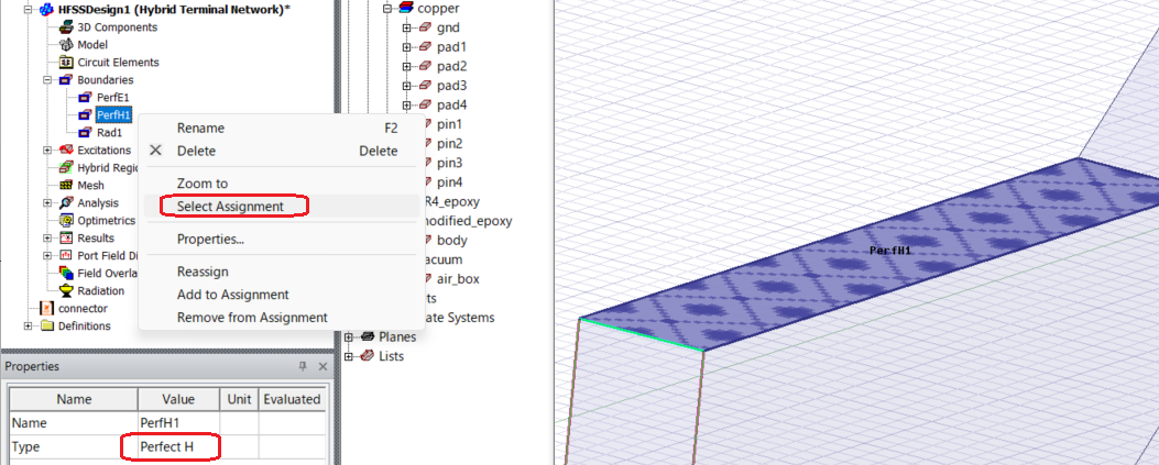
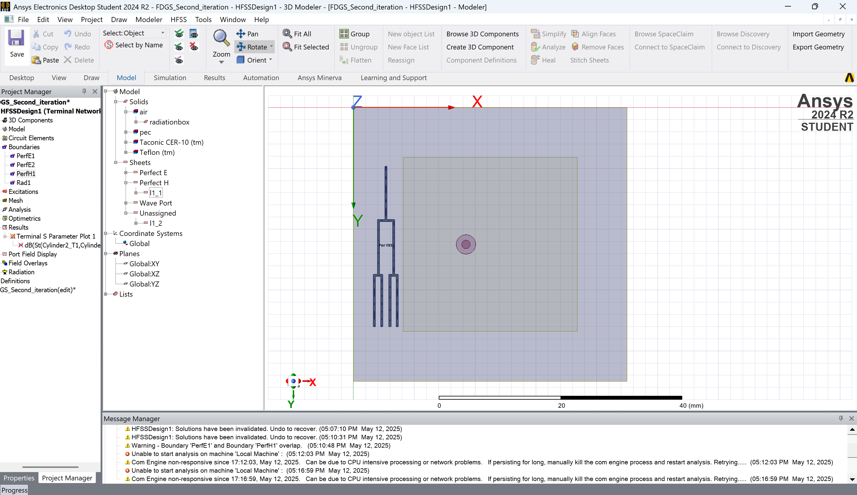
      In the Message Manager, there is a Warning for PerfE1 and PerfH1 overlap, you may want to raise the priority of PerfH1, right click on Boudaries in the Project Manager and select Reprioritize... Try to make PerfH1 the Highest.
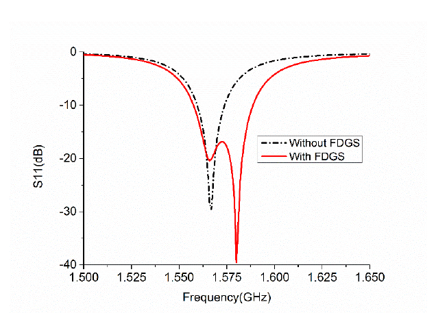
      If Altair FEKO is giving you the expected results, check the difference between the two settings.
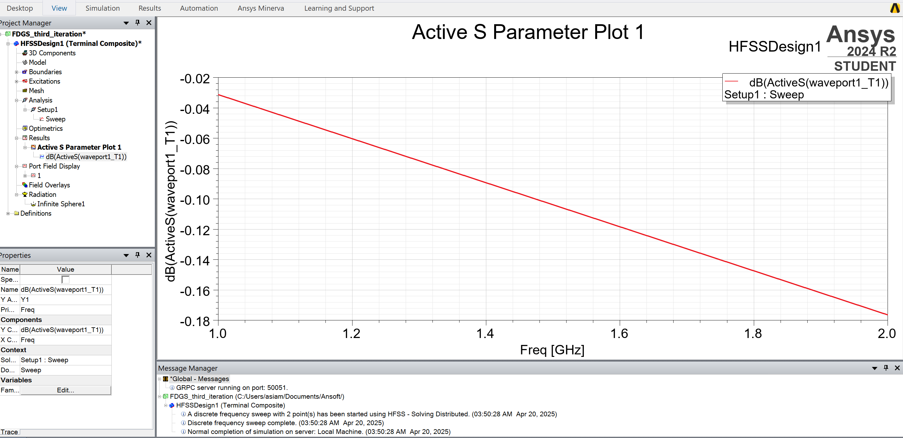
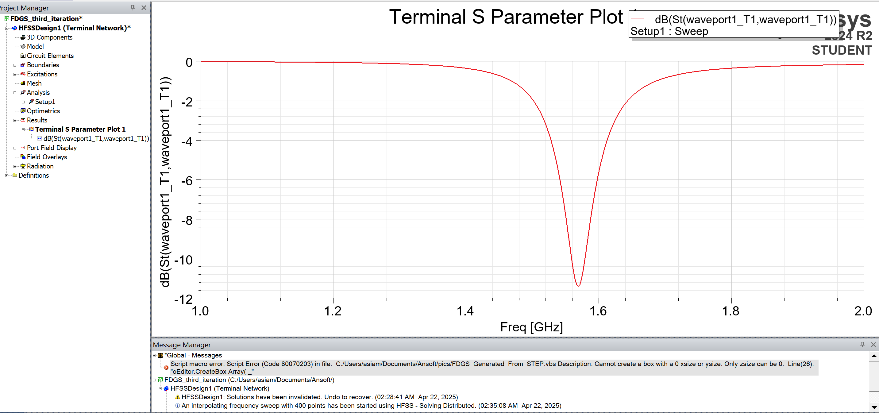
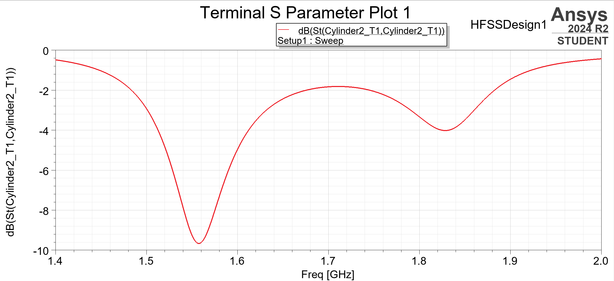
      Also, try lowering the Maximum Delta S value in Setup, as it may be a problem with the accuracy of the analysis.
      Also, if you are using Interpolating Sweep, consider using Discrete Sweep.

      • g24a8170
        Subscriber

        Thank you very much Takeshi Itadani, the model is now behaving as it should. I really appreciate your help.

Viewing 7 reply threads
  • You must be logged in to reply to this topic.
[bingo_chatbox]