TAGGED: ansys-electronics-desktop
-
-
August 21, 2024 at 3:26 am
vphase
SubscriberHi,
Here is my scheme:
I need to define the boundary conditions (lattice pairs) for the side walls. As you can see, the shape of the top layer is different, which has led to errors in the matching boundary conditions. I would like to know how I can address this issue.
I based this simulation on a shape described in a specific article.
Â
Â
-
August 23, 2024 at 9:16 am
vphase
SubscriberPlease Help me in the issue.
-
September 2, 2024 at 2:22 pm
Jason Kalogeropoulos
Ansys EmployeeHello Volter,Â
We appreciate your reaching out to Ansys Learning Forum.Â
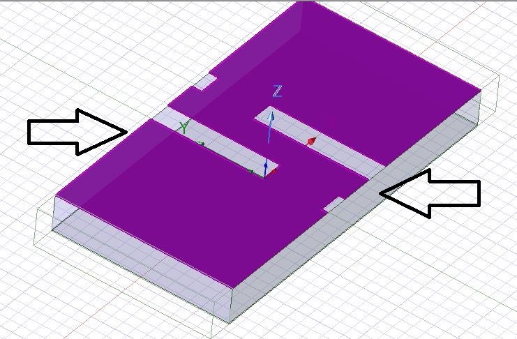
At a first point of view, please, make sure that you are using a symmetrical structure. This aims to make the lattice pairs to "see" identical meshes.Secondly, we would appreciate the fact of pointing out the errors and/or the mesh feedback in order to had a more robust image.
Since I am not 100% sure of the nature of the error that comes up, by experience, I would advice you to use the latest version (AEDT 24R2). Moreover, in 25R1 version, we have implemented a new approach leading to a flawless simulation considering the Lattice Pairs approach. Unfortunatelly, I am not able to provide an exact release date.Â
I hope this helps!Â
Kind regards,Â
Jason.Â
-
- You must be logged in to reply to this topic.
- Three-Phase Voltage Imbalances in dual stator electric generator
- Co-simulation in Q3D, Icepak – meshing problem
- Classic Icepak – clarifications on Boundary condition
- Link the Circuit to 3D Terminals
- Magnetic Dipole moment calculation
- Integration lines or U Axis Line for circular and rectangular ports
- Core Loss in ANSYS MAXWELL Eddy Current solution
- exporting and importing my Netlist for my external circuit
- Error of Metal Fraction in Icepak Classic.
- The unit of theta in Is*sin(2*pi*fre*Time+theta-2*pi/3)
-
4597
-
1495
-
1386
-
1209
-
1021
© 2025 Copyright ANSYS, Inc. All rights reserved.