-
-
July 13, 2021 at 3:50 pm
krishna4339
SubscriberDear @peteroznewman
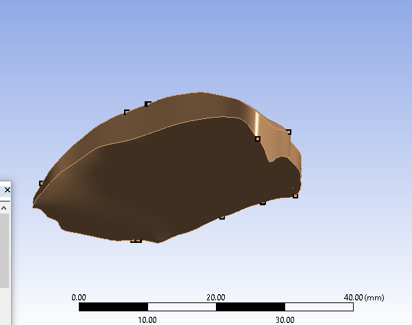
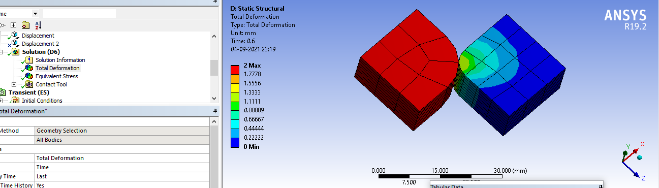
greetings of the day...i am trying to perform a static structural analysis of knee joint. My model involves 10 parts (including ligaments cartilage etc) and 13 contacts (frictional and bonded). To save time I tried to simplify the model and started experimenting on it.
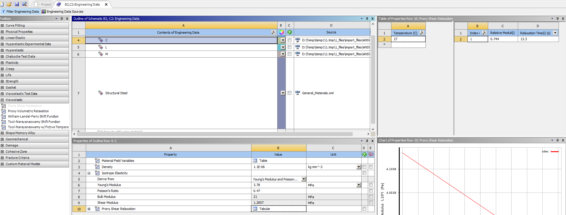
Mesh is created in Altair hypermesh software and it is exported as cdb file to Ansys wb.
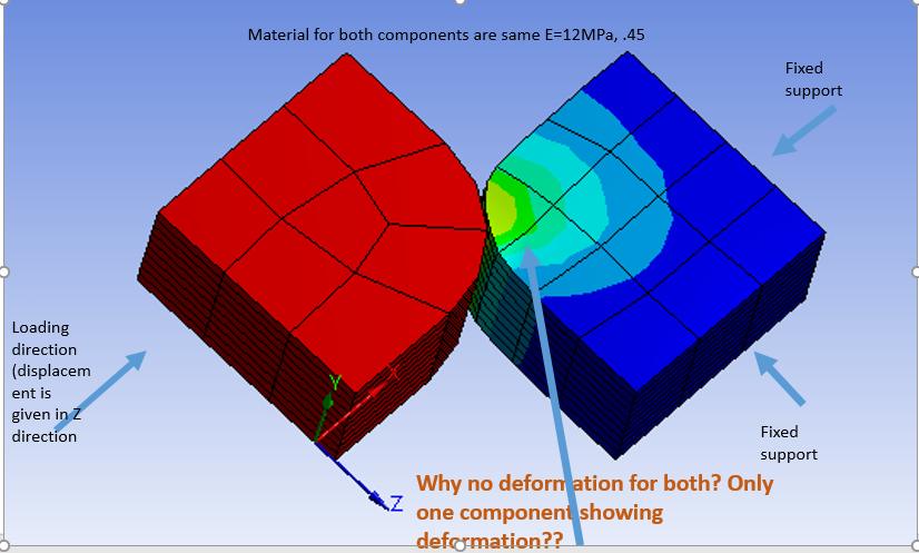
In ansys workbench i have created contacts,boundary conditions,loading.
I went through all discussions on biomechanic contacts in this forum before writing to you.
I also went through youtube tutorials by ansys learning page.
I have tried the following with respect to contact.
- different formulations tried with different detection methods to get convergence.
- changing the normal stiffness inorder to achieve convergence.
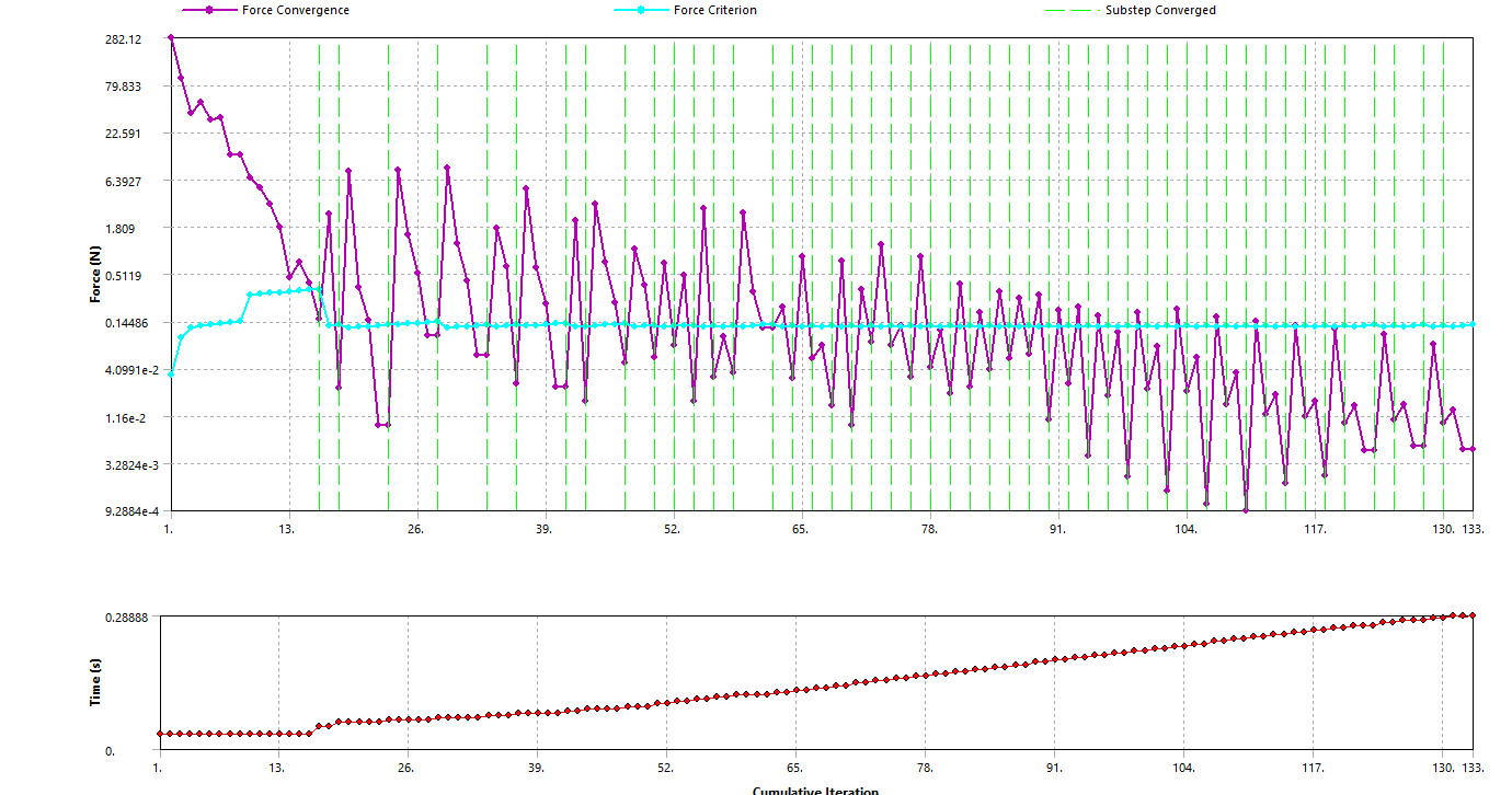
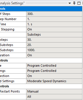
- increasing the number of substeps to apply displacement load slowly to achieve convergence
- tried changing the behavior of contact as explained in youtube video by ansys learning page.
- contact interface treatment also tried to change.
- mesh is refined using solid 185 elements in hypermesh.
- Even after all these i am not able to get the convergence.. Can you help?
- i can send the simplified model to you.
Thanks for your time and help. have a great day!.
July 13, 2021 at 4:26 pmkrishna4339
Subscriberwb archive file attached
July 14, 2021 at 12:48 ampeteroznewman
SubscriberI recommend the following to help convergence.
Use more elements through the thickness. A minimum of 4 linear elements should be used through the thickness. There are several places where there is only one element across the thickness.
Add Keyop(6)=1 to the Meniscus because that material is close to incompressible with a Poisson's Ratio of 0.49
Add Keyop(6)=1 to the Cartilage because that material is close to incompressible with a Poisson's Ratio of 0.45
Consider using Hyperelastic Material model for the Cartilage because that material has a low Young's Modulus.
July 15, 2021 at 5:12 pmkrishna4339
SubscriberDear Thanks for answers.
Part 1:
i cannot use more eleements at some of locations due to its dimensions. So i tried using higher order element solid 186.
keyop(6)=1 is used for all parts.
If i use hyperelastic material for cartilage i am afraid my solution will not converge, thats why i am testing with linear isotropic material.
after following all your suggestions, solution now converges upto 0.7 second. after that it stops converging. i have given displacement loadsteps upto 1 sec and increasing load gradually.
what else can be tried to improve convergence?
Am i making any mistakes , please let me know..
Part 2:
In my original model i have around 12 lakh element. Inorder to reduce the elements, i want to model bones as rigid and apply rotational displacement load on them about a particular axis. How can I do that?
I have both stl file and cdb files. Can i remove mesh belonging to bones from cdb and replace with bones stl file using space claim ? other wise workbench will not allow to define external mesh as rigid body behavior. I hope you understood the problem.
Thank you once again, have a great day!!
July 15, 2021 at 8:52 pmpeteroznewman
SubscriberI started a discussion to demonstrate how to converge STL files into Geometry that you might find helpful.
/forum/discussion/29718/convert-stl-of-knee-joint-to-geometry
I plan to make more videos to show the cartilage, meniscus and ligaments.
You can take your STL file and reprocess it to geometry then mesh with more elements through the thickness. Linear elements are more robust than quadratic elements for contact models.
I have seen models with linear elastic material properties that stopped convergence at some point and after the material was changed to hyperelastic, converged to the end.
You can make the bones rigid and use a rotational joint to rotate it about any axis you want. The joint is created with its own local Csys and you can put the origin anywhere and orient the Z rotation axis in any direction you want. The joint can be to ground or between two bodies.
July 19, 2021 at 3:36 pmkrishna4339
SubscriberThanks for inputs you have provided here in different posts. I could learn a lot of things from you. I made it a habit to follow your posts and youtube videos. Its very helpful. Best part is that i got the solution converged.
Have a great day!!
July 30, 2021 at 5:49 pmJuly 30, 2021 at 6:15 pmkrishna4339
Subscriberif not possible to mesh it using hexa, then i want to mesh it using tetra, but i want more layered mesh on the thickness.. how we can achieve that ?
July 30, 2021 at 7:21 pmpeteroznewman
SubscriberYou can make edits in SpaceClaim to get this geometry ready for hex meshing. It will be easier if you slice the part up into sweepable pieces. A sweepable piece has exactly the same number of edges on the top and the bottom face.
Is that the same geometry in the image as in the project archive a few posts above? If so, I can take a closer look. If not, you should upload a new archive with that geometry.
July 31, 2021 at 5:14 amkrishna4339
SubscriberYes it is the same geoemtry as it is in the archive.
Could you also suggest me what options in meshing can be used to achieve tetra hedral mesh? I need along the surface coarsal mesh and along thickness finer layered mesh.
i tried with inflation it didnt work.
thank you
July 31, 2021 at 12:55 pmpeteroznewman
SubscriberAugust 10, 2021 at 4:17 pmkrishna4339
Subscriber
greetings of the day!
i am facing problems during solution process.
solution is not comverging after 0.3 seconds. (total time is 1 sec)
i have attached solver output file.
Could you please look into it and help?
Thank you
have a nice day!
August 10, 2021 at 4:20 pmkrishna4339
Subscribercontact used : bonded(MPC FORMULATION) and frictional(NORMAL LAGRANGE).
Analysis involves both rigid and deformable bodies.
August 11, 2021 at 2:19 ampeteroznewman
SubscriberFirst there is a warning: Element 47783 (type = 11, SOLID185) (and maybe other elements) hasbecome highly distorted.Excessive distortion of elements is usuallya symptom indicating the need for corrective action elsewhere.Tryincrementing the load more slowly (increase the number of substeps ordecrease the time step size).You may need to improve your mesh toobtain elements with better aspect ratios.Also consider the behaviorof materials, contact pairs, and/or constraint equations.
Then there is the error that stops the solution: Element 47783 (SOLID185) is turning inside out.
Follow the advice given: Increment the load more slowly. That means in the step controls, try using: Initial Substeps = 100, Minimum Substeps = 100, Maximum Substeps = 1000.
August 19, 2021 at 1:56 pmkrishna4339
SubscriberGreetings of the day.
I have read in forum , where you said that its better to have shared topology than bonded contact or fixed joint between parts if possible as it would simplify the model to great extent. So I tried it. most of them worked but one of the contact it is not possible to define shared topology. I have attached the iges file. Could you look into it and help??? Thanks as always. Have a nice day.
August 19, 2021 at 10:50 pmpeteroznewman
SubscriberI'm traveling this weekend so won't be able to look at it until Monday.
August 23, 2021 at 10:15 amkrishna4339
Subscriber
greetings of the day
August 23, 2021 at 11:55 ampeteroznewman
SubscriberAttached is a SpaceClaim 2020 R2 document in a .7z archive.
The file you start with has gaps between the two solids.
The approach to making this work with Shared Topology is to copy the face from the bone, and rebuild the cartilage solid using that face and the side faces and the outer face. I have started that. Try and finish it yourself.
September 1, 2021 at 2:41 pmkrishna4339
Subscribergreetings of the day peter
how do we decide the perfect number of initial ,minimum and maximum substeps for the knee contact problem? i tried bigger steps got element distortion error, tried too small baby steps, so far converging. But in my 6 core machine it might take weeks to finish.
Thanks
September 1, 2021 at 2:44 pmkrishna4339
Subscriberattached a file below
September 1, 2021 at 3:18 pmSeptember 1, 2021 at 10:58 pmpeteroznewman
Subscriber300 steps with a minimum of 20 substeps = 6000 load increments and the solver seems to be taking 4 iterations to converge each increment, so you can estimate 24,000 iterations. Measure the time per iteration. Multiply that by 24,000 to estimate the time to finish.
You would be better off with just a few steps. That might allow the solver to take larger increments and reduce the total number of iterations.
You should also see if you can reduce the time per iteration by using fewer nodes. See if the Direct Solver or the Iterative Solver takes less time per iteration.
September 4, 2021 at 4:53 pmkrishna4339
SubscriberDear peter, Greetings of the day.
I am still learning alot of things with contact modeling. Now i tried a simple contact problem (Check snapshot). My question is how to get deformation results and contact pressure for both components. I have tried whatever I have learnt so far.I must be missing something.Could you take a look ??
I have played around mesh,contact behavior,formulations , stepsize , even changed type of analysis to transient from static. Still no change.
Thanks
September 4, 2021 at 5:02 pmpeteroznewman
SubscriberI don't know what result you are plotting or what the colors mean. You didn't include the legend in the image. Please provide an image that shows the legend.
September 4, 2021 at 6:03 pmkrishna4339
SubscriberSorry. I thought that may not be relevant. It is a deformation plot.
attached here , update: when i changed the friction coefficient from 0.002 to 0.1 i got contact pressure on both contact and target faces. But why the deformation is only on one body? since they are having same material, shouldnt they deform by same amount wrt each other ??
September 4, 2021 at 6:54 pmpeteroznewman
SubscriberIt looks like the moving body had to travel 1 mm before the fixed body made contact with it.
Plot the contact pressure vs time.
September 4, 2021 at 7:04 pmkrishna4339
SubscriberWhy does it matter ? Even if it travels when they contact each have to deform wrt each other ... could u explain ?September 5, 2021 at 2:39 ampeteroznewman
SubscriberDeformation is relative to the starting location of each node, so it matters that one body travelled 1 mm before contact.
Plot Strain to see the local deformation of each element with respect to its initial shape, regardless of how far it had to travel before contact was made. The same goes for Stress.
September 6, 2021 at 1:18 pmkrishna4339
Subscribergreetings of the day!
How to enter prony series data which contains 3 paramters in ansys engineering data??
snapshots attached are
prony test data from literaure
Equations used for the prony series. (its not maxwell model )
ansys visco elastic table from engineering data
September 6, 2021 at 1:18 pmSeptember 6, 2021 at 1:18 pmSeptember 6, 2021 at 1:18 pmSeptember 7, 2021 at 1:00 pmkrishna4339
Subscribergreetings of the day.
with respect to above post in the help i was able to find that both bulk and shear moduli data to be entered seperately. But how to do it in engineering data ? also where to add initial young's modulus and poissons ratio ?
Can you help?
thanks
Viewing 32 reply threads- The topic ‘Knee joint contact problem leading to convergence issues’ is closed to new replies.
Ansys Innovation SpaceTrending discussions- The legend values are not changing.
- LPBF Simulation of dissimilar materials in ANSYS mechanical (Thermal Transient)
- Convergence error in modal analysis
- APDL, memory, solid
- How to model a bimodular material in Mechanical
- Meaning of the error
- Simulate a fan on the end of shaft
- Nonlinear load cases combinations
- Real Life Example of a non-symmetric eigenvalue problem
- How can the results of Pressures and Motions for all elements be obtained?
Top Contributors-
3862
-
1414
-
1231
-
1118
-
1015
Top Rated Tags© 2025 Copyright ANSYS, Inc. All rights reserved.
Ansys does not support the usage of unauthorized Ansys software. Please visit www.ansys.com to obtain an official distribution.
-

Ansys Assistant

Welcome to Ansys Assistant!
An AI-based virtual assistant for active Ansys Academic Customers. Please login using your university issued email address.

Hey there, you are quite inquisitive! You have hit your hourly question limit. Please retry after '10' minutes. For questions, please reach out to ansyslearn@ansys.com.
RETRY