Ansys Assistant will be unavailable on the Learning Forum starting January 30. An upgraded version is coming soon. We apologize for any inconvenience and appreciate your patience. Stay tuned for updates.
Electronics

Electronics

Topics related to HFSS, Maxwell, SIwave, Icepak, Electronics Enterprise and more.

Interaction between the different shape FSS unit cell

    • hyhaerong
      Subscriber

      Hi Ansys Innovation Space Community,

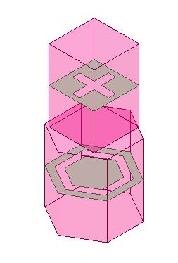
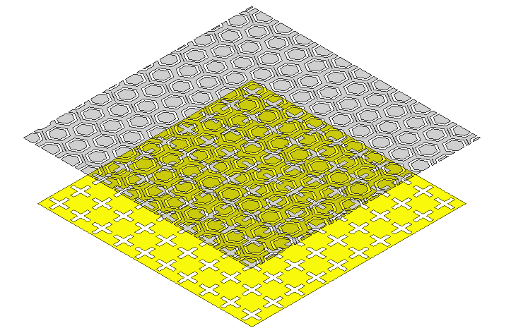
      I am trying to simulate the double-layered FSS from two different-looking unit cells.

      However, I cannot find a clue to set the unit cell and Floquet port.

      For instance, if I want to simulate between the cross-unit cell and hexagon unit cell,

      How should I set the air box and the port?

      Since I didn't know how to run it, I just made a big square array and I saw the error messages like below.

          [warning] In Master_To_Slave map, body Polygon2 has multiple contacts. Its Primary contact is body Polygon2. Its secondary contact is body {Box1} (6:28:51 PM  Jan 16, 2023)
          [warning] In Master_To_Slave map, body Box1 has multiple contacts. Its Primary contact is body Box1. Its secondary contacts are bodies {Polygon2, Polygon2_1} (6:28:51 PM  Jan 16, 2023)
          [warning] In Master_To_Slave map, body Polygon2_1 has multiple contacts. Its Primary contact is body Polygon2_1. Its secondary contact is body {Box1} (6:28:52 PM  Jan 16, 2023)
          [warning] In Slave_To_Master map, body Polygon2 has multiple contacts. Its Primary contact is body Polygon2. Its secondary contact is body {Box1} (6:28:52 PM  Jan 16, 2023)
          [warning] In Slave_To_Master map, body Box1 has multiple contacts. Its Primary contact is body Box1. Its secondary contacts are bodies {Polygon2, Polygon2_1} (6:28:52 PM  Jan 16, 2023)
          [warning] In Slave_To_Master map, body Polygon2_1 has multiple contacts. Its Primary contact is body Polygon2_1. Its secondary contact is body {Box1} (6:28:52 PM  Jan 16, 2023)
          [warning] Matching boundary process might encounter unexpected conditions because the contact maps are ambiguous. Ending this meshing attempt, starting the next attempt. (6:28:52 PM  Jan 16, 2023)
          [error] Body vertex has no link to model vertex. Promoting this to fatal error now. (6:28:52 PM  Jan 16, 2023)
          [warning] Found 12 topologically unmatchable vertex points in the input mesh. Proceeding with experimental algorithm, unexpected conditions might be encountered in the matching process. Ending this meshing attempt, starting the next attempt. (6:30:12 PM  Jan 16, 2023)
          [error] Body vertex has no link to model vertex. Promoting this to fatal error now. (6:30:12 PM  Jan 16, 2023)
          [info] Parametric Analysis is done. (6:30:12 PM  Jan 16, 2023)


      Is there anyone who knows how to simulate the interaction between the two different FSS?

    • Praneeth
      Ansys Employee

      Hi,

      I could not understand fully what your requirement is. Please provide more details to help us serve you better.

      Following are some preliminary suggestions that can help you -

      1. How are the "cross" and "hexagon" portions designed in the tool?
      2. Are the "cross" and "hexagons" made of conductor material?
      3. Is there any dielectric material placed between these two FSS structures?
      4. I see that there is some offset between the centers of these two structures. Is that why you were not able to define the unit cell?

      Best regards,
      Praneeth.

      • hyhaerong
        Subscriber

        Really appreciate your response.

        1. I don't understand the question with the first one. I don't know this could be an answer, I usually follow the youtube video below
        2. Those are Perfect E sheets.
        3. Just an air gap. I just want to see what will happen if I put two different FSS pattern put together
        4. when it comes to simulating in a unit cell, I don't know how to make an air box and assign a Floquet port.

          I will attach a link to the youtube video that I used as a reference.
          https://www.youtube.com/watch?v=cQpoyQrhppc
          The problem that I have is when there are two different shapes of FSS and if I want to put it together (or overlap with a gap), How I should simulate it through the HFSS.
    • Praneeth
      Ansys Employee

      Hi,

      Thank you for your response and your patience is much appreciated.

      If you want to simulate a single unit cell for both the structures, then you need to design a single lattice for both with some air gap. You cannot place two different lattice shapes on top of each other and simulate it. You need to convert the square lattice into hexagonal one and simulate your model. Remember that you need to use three pairs of coupled boundaries for hexagonal lattice rather than two pairs as for a general square lattice.

      If you new to coupled boundaries and Floquest port then I suggest you to go through this free course from Ansys - Ansys HFSS Floquet Port - ANSYS Innovation Courses, Microstrip Patch Antenna Finite Array Creation Using Domain Decomposition Method in Ansys HFSS — Lesson 5 - ANSYS Innovation Courses.

      Best regards,
      Praneeth.

Viewing 2 reply threads
  • The topic ‘Interaction between the different shape FSS unit cell’ is closed to new replies.
[bingo_chatbox]