

TAGGED: core, electronics, inductance, transformer
-
-
January 22, 2021 at 8:58 am
icj96
SubscriberHello Ansys Community!
I am tasked to find the inductance of a core with a given geometry (Epcos E19/8/5), material (TKD N87) and an air gap of 0.5mm. The geometry was imported from grabcad and material was input manually with a relative permeability of 2200.
From my analytical calculation, the total reluctance of this design is 36002774.55.
1) Turn Ratio * Current = Magnetic Flux * Reluctance, where Magnetic Flux can be interpretted as B * Ae
with Turn Ratio = 12, Current = 10, Ae = 22.5mm^2 (from datasheet), Reluctance = 36002774.55,
B = 0.148
2) Inductance * Current = Turn Ratio * Magnetic Flux, where Magnetic Flux can be interpretted as B * Ae
with Current = 10, Turn Ratio = 12, B = 0.148, Ae = 22.5mm^2,
Inductance = 4microH (approximate value, L = (Turn Ratio)^2 / Reluctance can be used too)
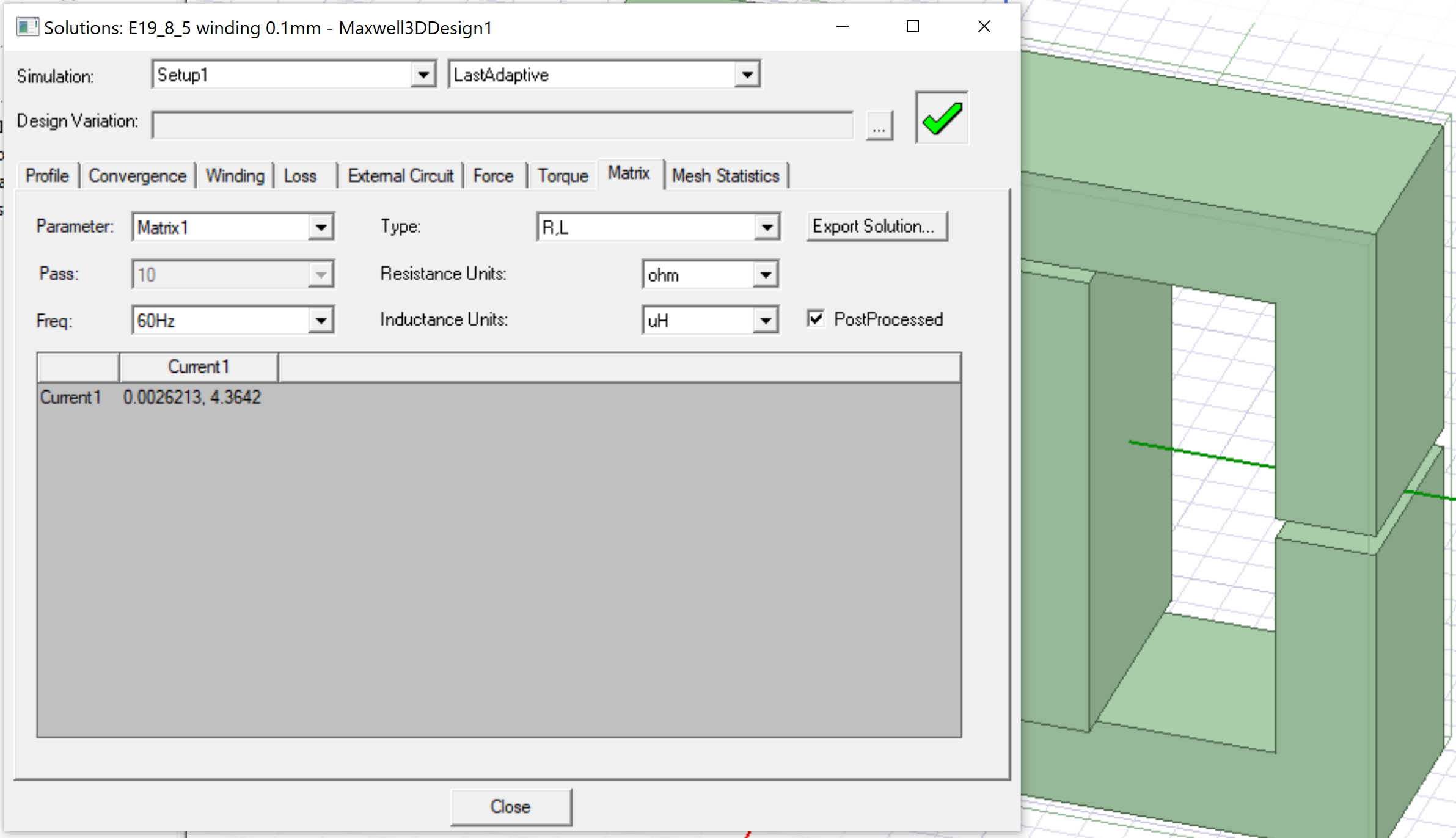
As seen in the attached pictures, the inductance value is 6.9microH, which is different from my analytical calculation. Is there any mistake in my simulation?
Thank you in advance!
CJ
January 26, 2021 at 1:44 amicellb1
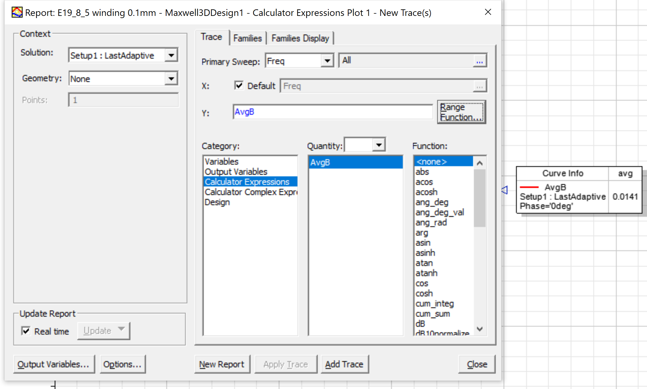
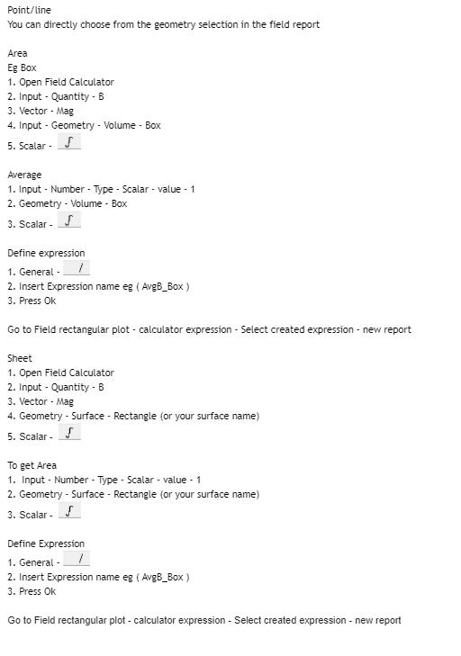
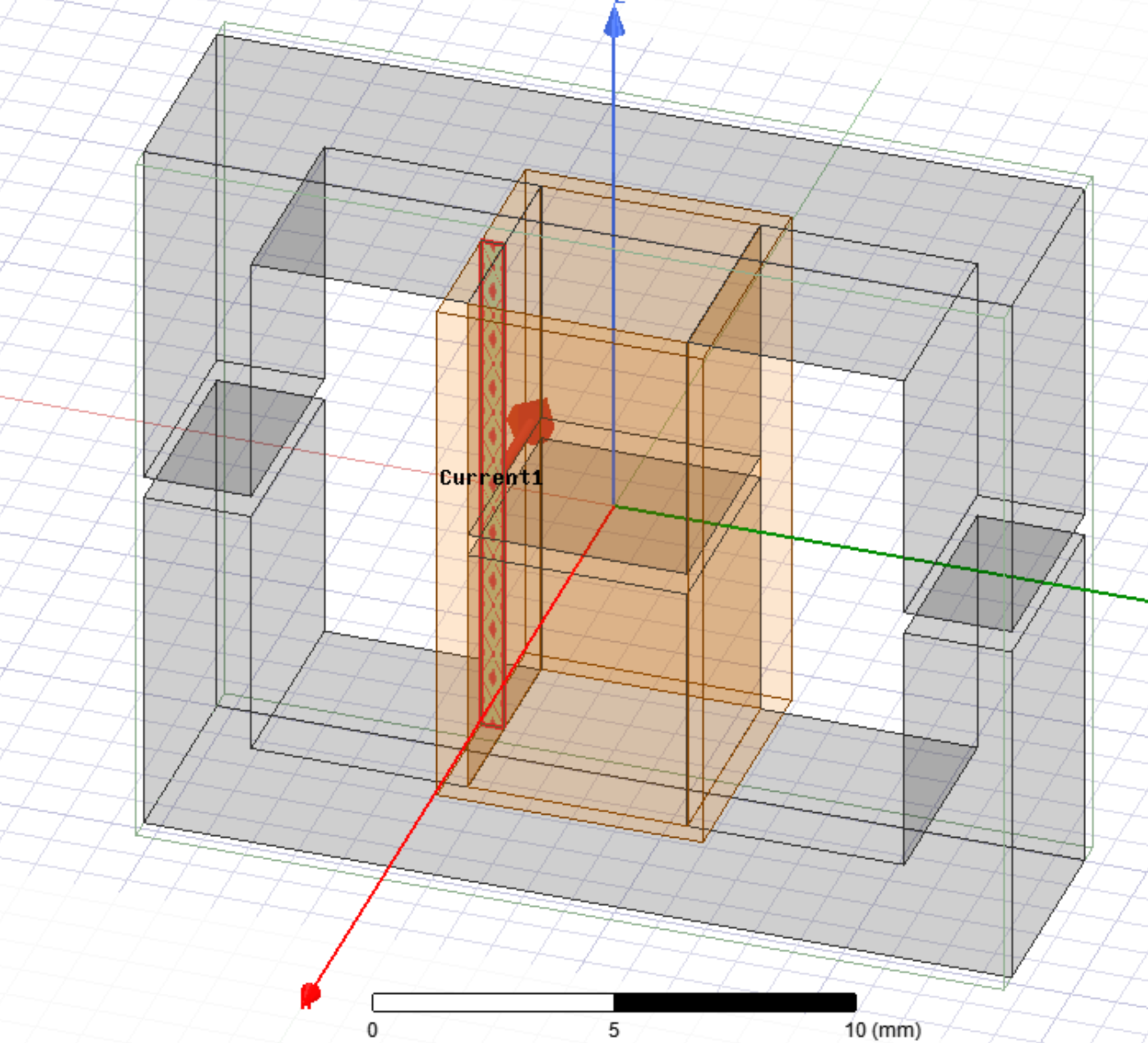
Ansys EmployeeHi,nMay I ask how you obtained the value B=0.148 T for analytical calculation? If the B from your simulation is different from you B for calculation, then the inductance result should also be different. Also, did you put a 0.5 mm gap between all 3 legs of the transformer model in maxwell? If so, the total air gap is much larger and will decrease inductance. nJanuary 28, 2021 at 2:55 amSubscribernThank you for your reply. In regards to your queries, 1) Regarding the value of B=0.148T, I have attached a picture with my workings. 2) Yes, I designed a 0.5mm gap on all 3 legs. nJust to clarify my workings, to determine the number of turns, I have used 5uH to determine the turn ratio and rounded down for a better estimation when using Ansys.nIce, how do I know the value of B from simulation? Or, is there an input option for me to enter my B? I do not remember seeing any B input when simulating. nThank you for your response!nnMarch 10, 2021 at 6:10 pmAnsys EmployeeHi,nWe are not allowed to click into a link or picture. Could you use upload image rather than upload File to show a displaying/visible screenshot? nAlso, if your calculation is based on air gap=0.5 mm, putting a 0.5 mm gap inallthree legs in simulation will result in much smaller L than your calculated L. nMarch 16, 2021 at 9:34 amSubscribernThe first picture is my analytical calculation of reluctance, the estimated number of turns, B-field and estimated inductance value to be obtained.nThe second picture is my simulated inductance value with the parameters of 10A and 12turns.nThe third picture is my B-field calculated using a field calculator with the inputs followed in the fourth picture. The simulated B-field, 0.014T does not tally with my analytical B-field, 0.14T.nThe fourth picture is my design. The coil is not touching the core with a 0.1mm allowance between. nI have some queries hoping that you can clarify for me,n1) Why does changing the amount of padded region changes the inductance value? E.g. 0 padded region yield 4.4uH and 100 padded region yield 8.1uHn2) I was told that to obtain an identical B-field for analytical and simulated, adaptive meshing is needed. How do I perform adaptive meshing? Or, is there another way to obtain an identical B-field?n3) I am also required to calculate the leakage inductance of this design. Is there a guide that I can refer to?nThank you in advance!n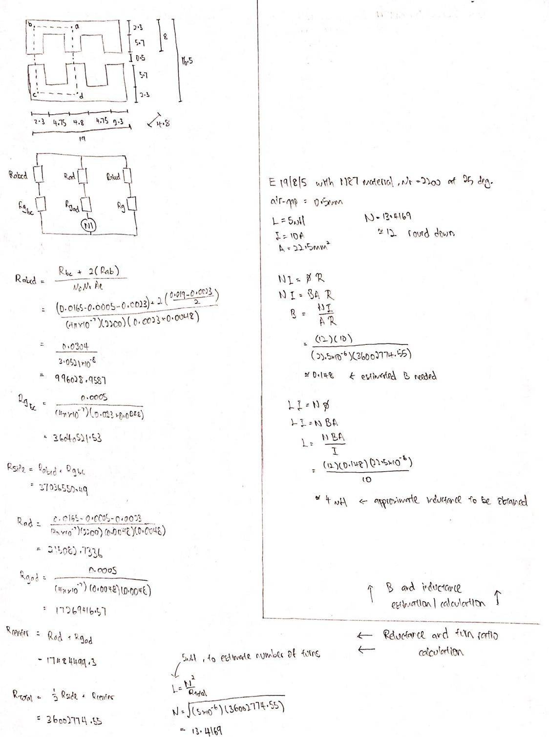
 n
March 22, 2021 at 10:07 pmAnsys EmployeeHi,n1) Why does changing the amount of padded region changes the inductance value? E.g. 0 padded region yield 4.4uH and 100 padded region yield 8.1uHnThe region decides within which volume maxwell do analysis and account fields to get impedances, theoretically the larger the region the closer to reality result you will get because there is always fields not confined within your geometry volume and dispersed in the region. However since having larger region increases simulation time, it's better to have an appropriate size of region. The common practice is to do gradually enlarge/or decrease the region size until you find there is not much difference in results when you change region size.n2) I was told that to obtain an identical B-field for analytical and simulated, adaptive meshing is needed. How do I perform adaptive meshing? Or, is there another way to obtain an identical B-field?nBy default there's adaptive meshing in eddy current solver. If you right click setup1>convergence, you will see as # of passes increases, # of tetrahedral increases while energy error and delta energy decreases. This is the adaptive meshing procedure. If you set the percent error to a smaller value in your setup1 if you want the adaptive meshing to be performed more extensively and get more accurate results.n3) I am also required to calculate the leakage inductance of this design. Is there a guide that I can refer to?nThis is answered in the other post of yours: Leakage inductance calculation for transformer model ? Ansys Learning ForumnViewing 5 reply threads
n
March 22, 2021 at 10:07 pmAnsys EmployeeHi,n1) Why does changing the amount of padded region changes the inductance value? E.g. 0 padded region yield 4.4uH and 100 padded region yield 8.1uHnThe region decides within which volume maxwell do analysis and account fields to get impedances, theoretically the larger the region the closer to reality result you will get because there is always fields not confined within your geometry volume and dispersed in the region. However since having larger region increases simulation time, it's better to have an appropriate size of region. The common practice is to do gradually enlarge/or decrease the region size until you find there is not much difference in results when you change region size.n2) I was told that to obtain an identical B-field for analytical and simulated, adaptive meshing is needed. How do I perform adaptive meshing? Or, is there another way to obtain an identical B-field?nBy default there's adaptive meshing in eddy current solver. If you right click setup1>convergence, you will see as # of passes increases, # of tetrahedral increases while energy error and delta energy decreases. This is the adaptive meshing procedure. If you set the percent error to a smaller value in your setup1 if you want the adaptive meshing to be performed more extensively and get more accurate results.n3) I am also required to calculate the leakage inductance of this design. Is there a guide that I can refer to?nThis is answered in the other post of yours: Leakage inductance calculation for transformer model ? Ansys Learning ForumnViewing 5 reply threads- The topic ‘Inductance calculation of a transformer core’ is closed to new replies.
Innovation Space Trending discussions
 Top Contributors
-
peteroznewman
 5849
5849 -
scabo
 1906
1906 -
Dennis Chen
 1420
1420 -
javat33489
 1305
1305 -
Shyam Prasad V Atri
1021
Top Rated Tags
© 2026 Copyright ANSYS, Inc. All rights reserved.
Ansys does not support the usage of unauthorized Ansys software. Please visit www.ansys.com to obtain an official distribution.
-


