TAGGED: fluent, mixed-convection, reverse-flow
-
-
July 19, 2021 at 10:41 am
Thirumoorthy
SubscriberHi all,
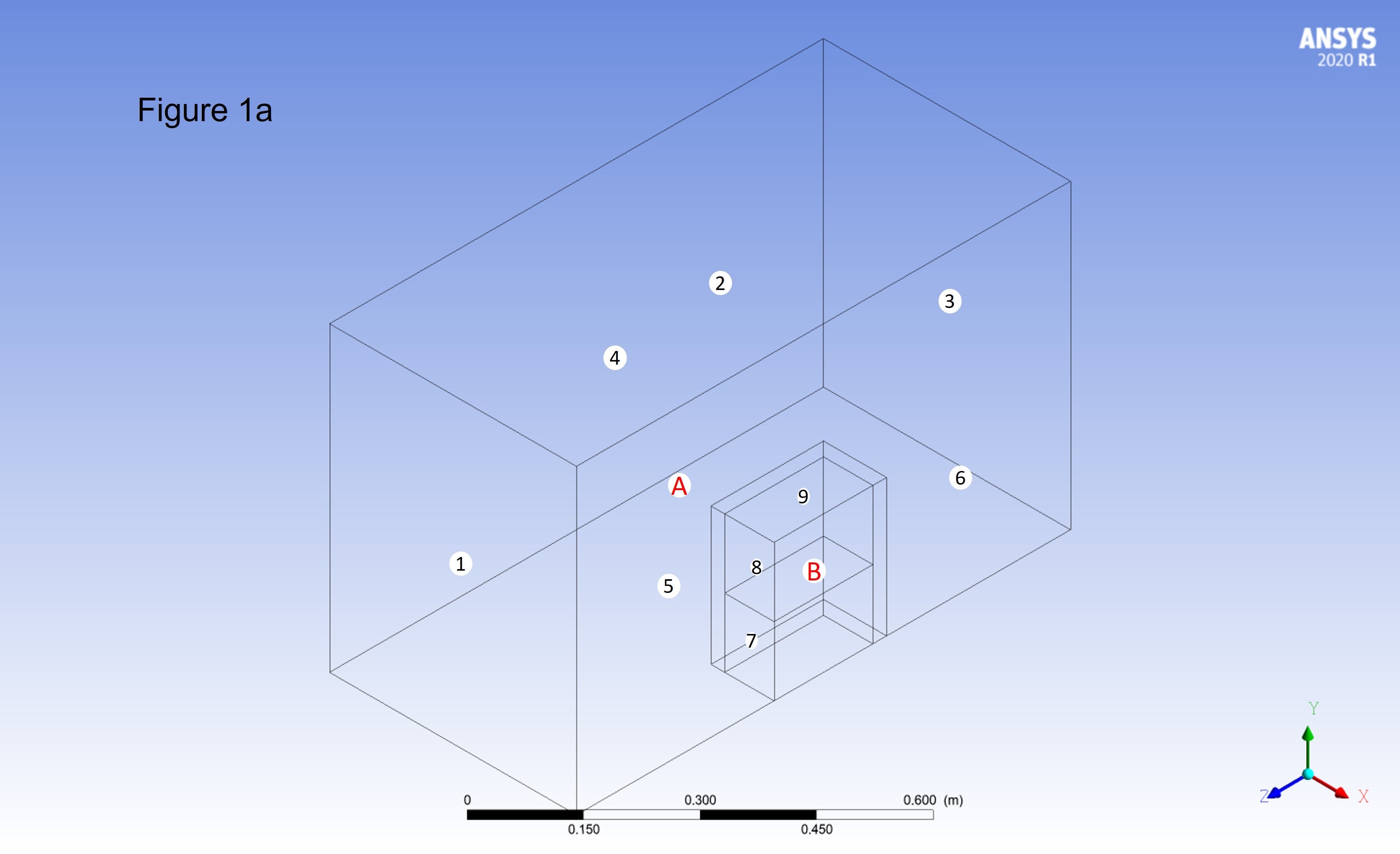
Symmetrical Geometry (figure 1a), explanations: A square cross-sectioned fume hood chamber ('A') having only a front opening, and a square cross-sectioned cookstove ('B') placed inside in it. Cookstove wall (solid) has some thickness which is also presented in the fluid domain. Cookstove ('B') has two different fluid heat generation sources inside it, divide as lower and upper parts of the cookstove. The lower part of the cookstove has the porous region heat generation and the upper part is the non-porous heat generation region.
Models used in fluent: Steady-state, turbulent (k-epsilon, standard wall function), hot flow. Working fluid is air, density calculated using ideal gas law (gravity is on). Simulating a mixed convection flow: Airflow to the cookstove is driven by buoyancy (two different heat generation sources) and also by pressure drop at the outlet plane of fume hood.
Boundary conditions: a. ('1', XY plane) Pressure inlet (Gauge Pr = 0 Pa), b. ('2', XZ plane) Pressure outlet (Gauge Pr is few Pa of negative Pr); c. ('3'), ('4'), and ('5') are the constant temperature wall boundaries. d. ('6') is symmetry face
Interfaces: ('7') is the air entry face in the porous region, ('8') is the air entry face in the non-porous region, and ('9') is the total air exit from the cookstove.
July 19, 2021 at 10:57 amRob
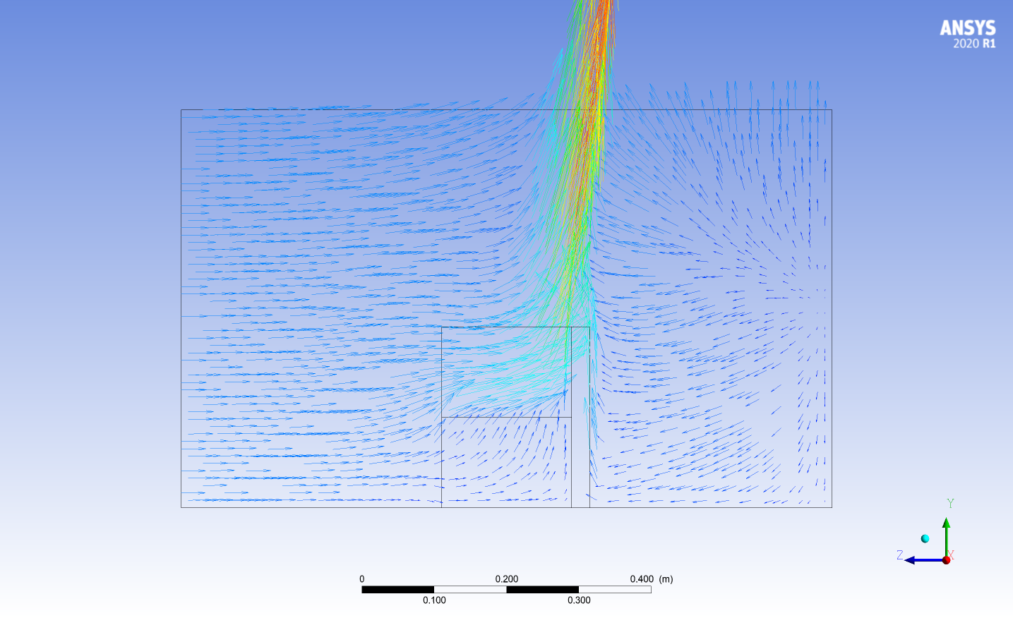
Forum ModeratorStaff are not permitted to open or download attachments so please repost the images. Blocking reverse flow tends to give an artificial solution is isn't advised unless you know why you want to use it and why it's not going to alter your answer. Extending the domain is the solution. If you did that and didn't label or connect (share topology) the additional fluid zones you may find one or more is a solid, or that you have badly defined contact interface regions. If you can plot and post pathlines from the inlet it'll be clearer what's going on.
July 19, 2021 at 11:22 amSubscriber@Rob I reposted the images, please see them and leave comments.
July 19, 2021 at 1:48 pmForum ModeratorThanks
What operating density did you set? Given the flow velocity I'd use incompressible ideal gas as you're nowhere near 0.3M
July 20, 2021 at 8:30 amSubscriberYes, am calculating operating density using the incompressible ideal gas, which I already mentioned in post 1.
July 20, 2021 at 10:11 amForum ModeratorOperating density is set in the Operating Conditions panel, it's a fixed point used in some calculations and is not the same as the gas density. If you've not set that it may explain some of the flow features.
Initialise the model using the "outside" temperature and pressure (use the outside boundary and "standard initialisation". Then report the volume density. Use that value (to all 5-6 decimal places) in the operating conditions and re-run. Do not use "prevent reverse flow".
July 20, 2021 at 3:22 pmSubscriberYes, specifying operating density in operating conditions panel is working. It seems that using incompressible ideal gas for density calculation in natural convection, specifying operating density is necessary
 .
.
July 20, 2021 at 4:07 pmForum ModeratorRead the background theory: it's obvious when you know but not as clear as it ought to be.
July 20, 2021 at 4:32 pmSubscriberOK. Thanks a lot.
Viewing 8 reply threads- The topic ‘How to prevent reverse flow without altering the nature of flow?’ is closed to new replies.
Innovation Space Trending discussions
 Top Contributors
-
peteroznewman
 4683
4683 -
scabo
 1565
1565 -
Dennis Chen
 1386
1386 -
javat33489
 1242
1242 -
Shyam Prasad V Atri
1021
Top Rated Tags
© 2025 Copyright ANSYS, Inc. All rights reserved.
Ansys does not support the usage of unauthorized Ansys software. Please visit www.ansys.com to obtain an official distribution.
-