Hello Everyone,
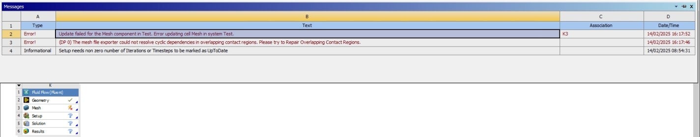
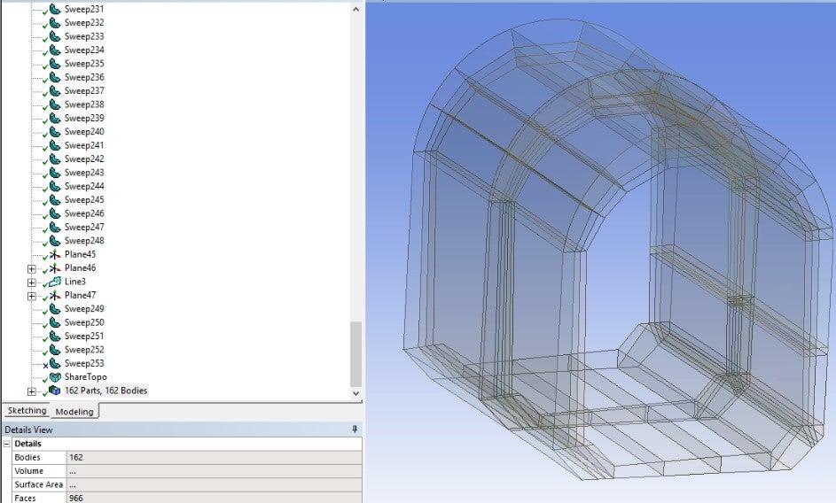
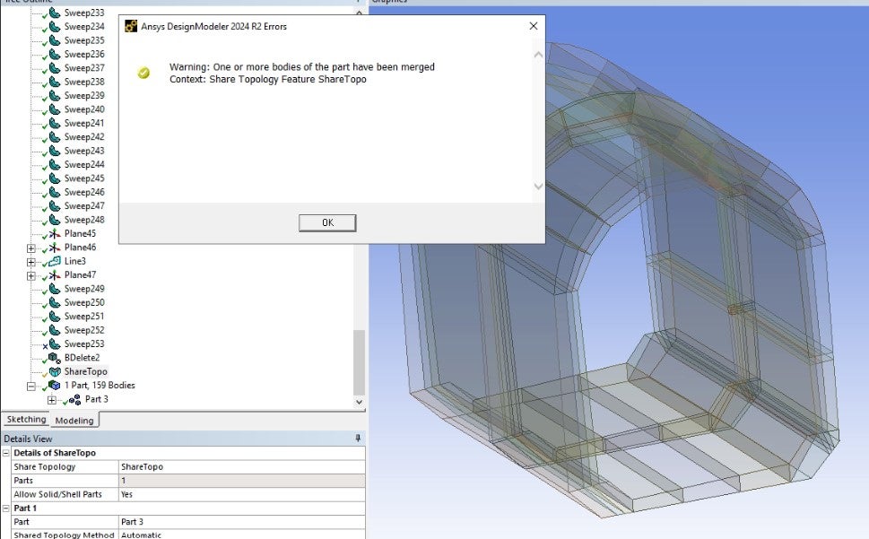
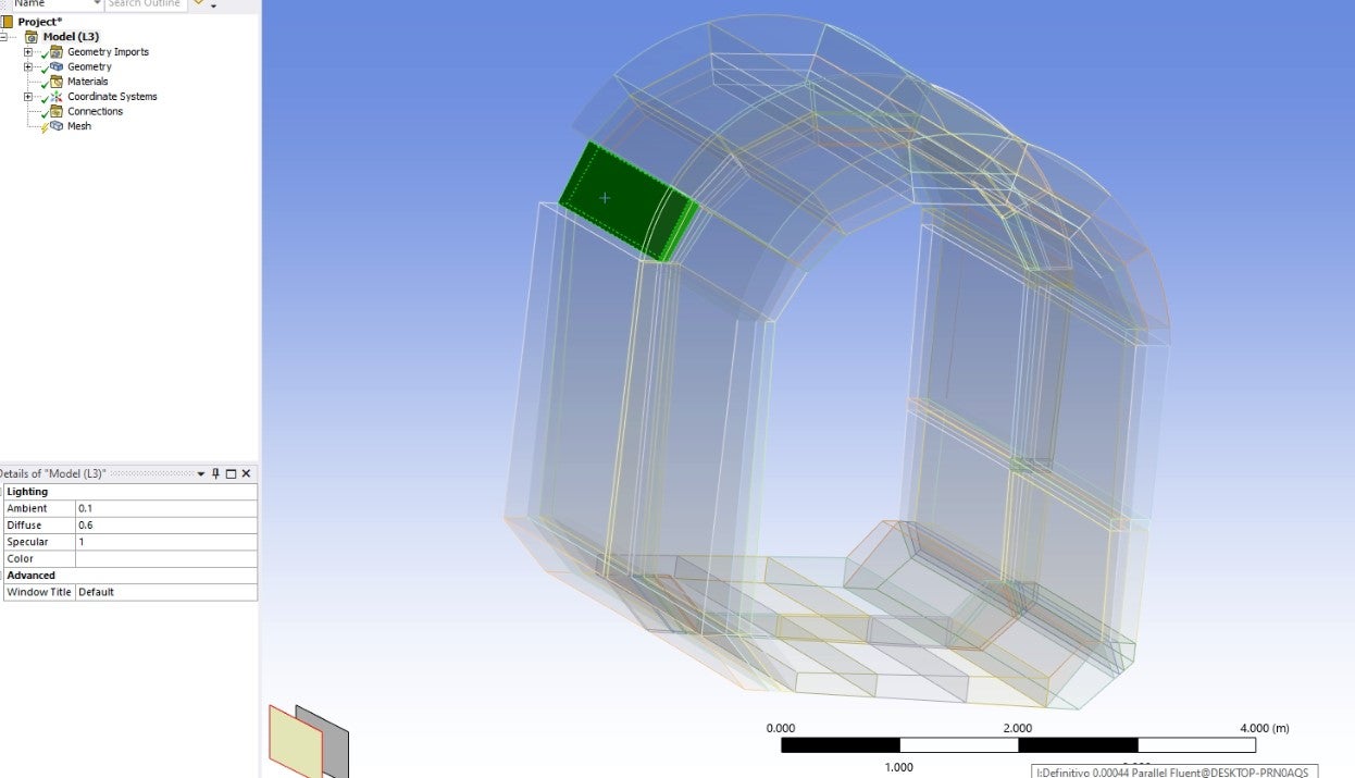
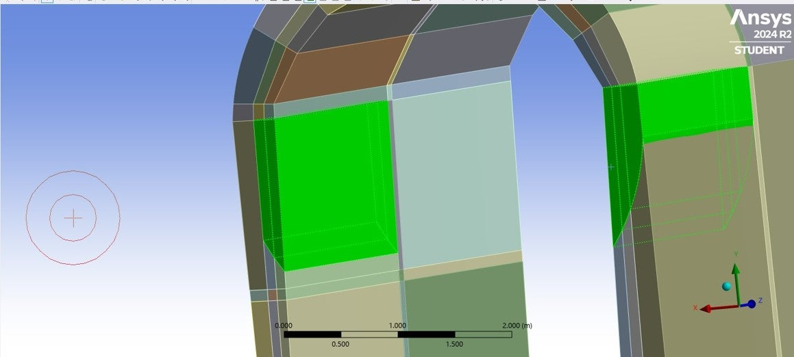
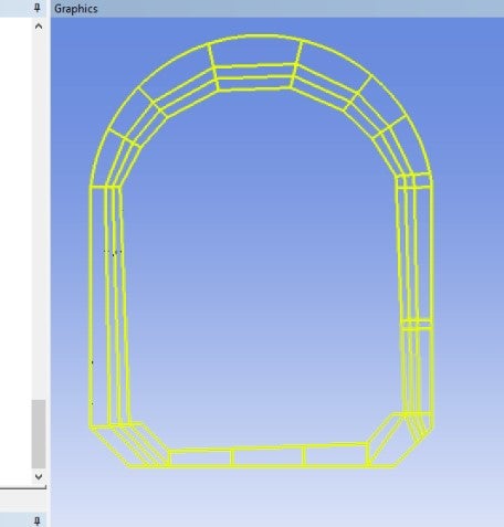
I am working with Fluent on a multibody geometry. During the meshing process, I manually create the connections between all the bodies because the automatic connection generation does not capture all of them.
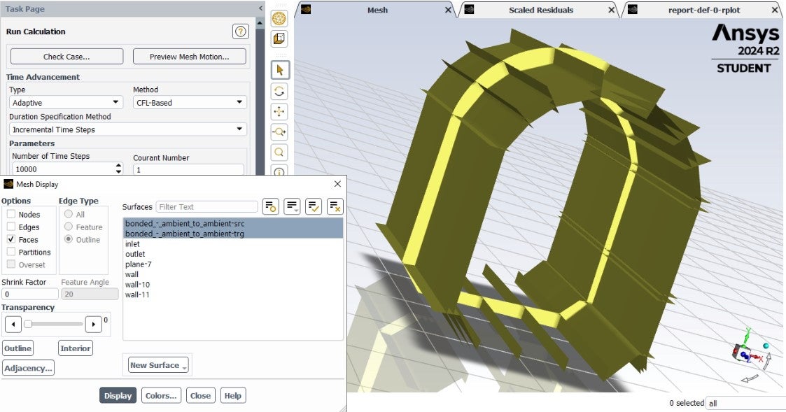
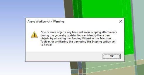
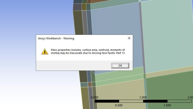
When I run the simulation in Fluent, it starts, but the software displays the following message:
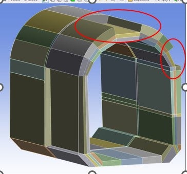
Info: Interface zones, 8 and 9, possibly penetrate each other. This could adversely affect your solution.
I suspect that this issue is affecting my results.
How can I locate the referenced zones 8 and 9 in the mesh?
Thank you! 😀