

-
-
December 1, 2021 at 3:59 pm
safiana
SubscriberHi everyone,
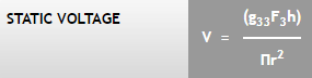
I am modeling piezoelectric ceramics in ANSYS APDL for force sensing application. After defining the material and applying a certain load to the PZT disk, I can get a voltage value from the disk. But this voltage is in open circuit condition. For example, by running the modeling in transient analysis and applying a dynamic load, the voltage signal exactly follows the strain signal, and of course, the value of voltage is too high like 30V. I could verify the voltage amplitude by the following equation to make sure my modeling steps are correct:
December 3, 2021 at 4:53 pmBill Bulat
Ansys EmployeeHello Ali
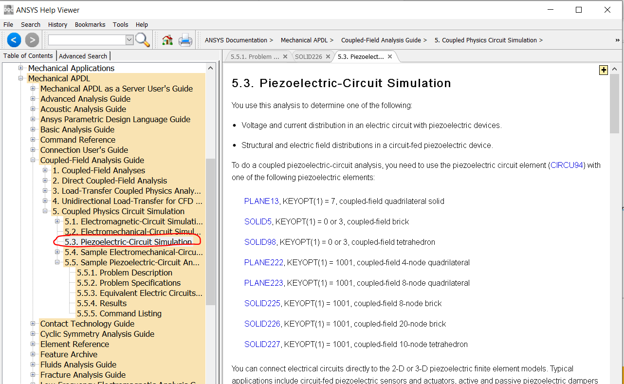
We can couple CIRCU94 elements to the electrodes of piezoelectric elements modeled with charge-based SOLID226/227 (keyopt(1)=1001):
I'm quite certain we can also couple CIRCU124 to current-base SOLID226/227 (keyopt(1)=101).
Your objective reminds me of the worked example in the Help below, which demonstrates setup of equivalent circuit model of a piezoelectric device:
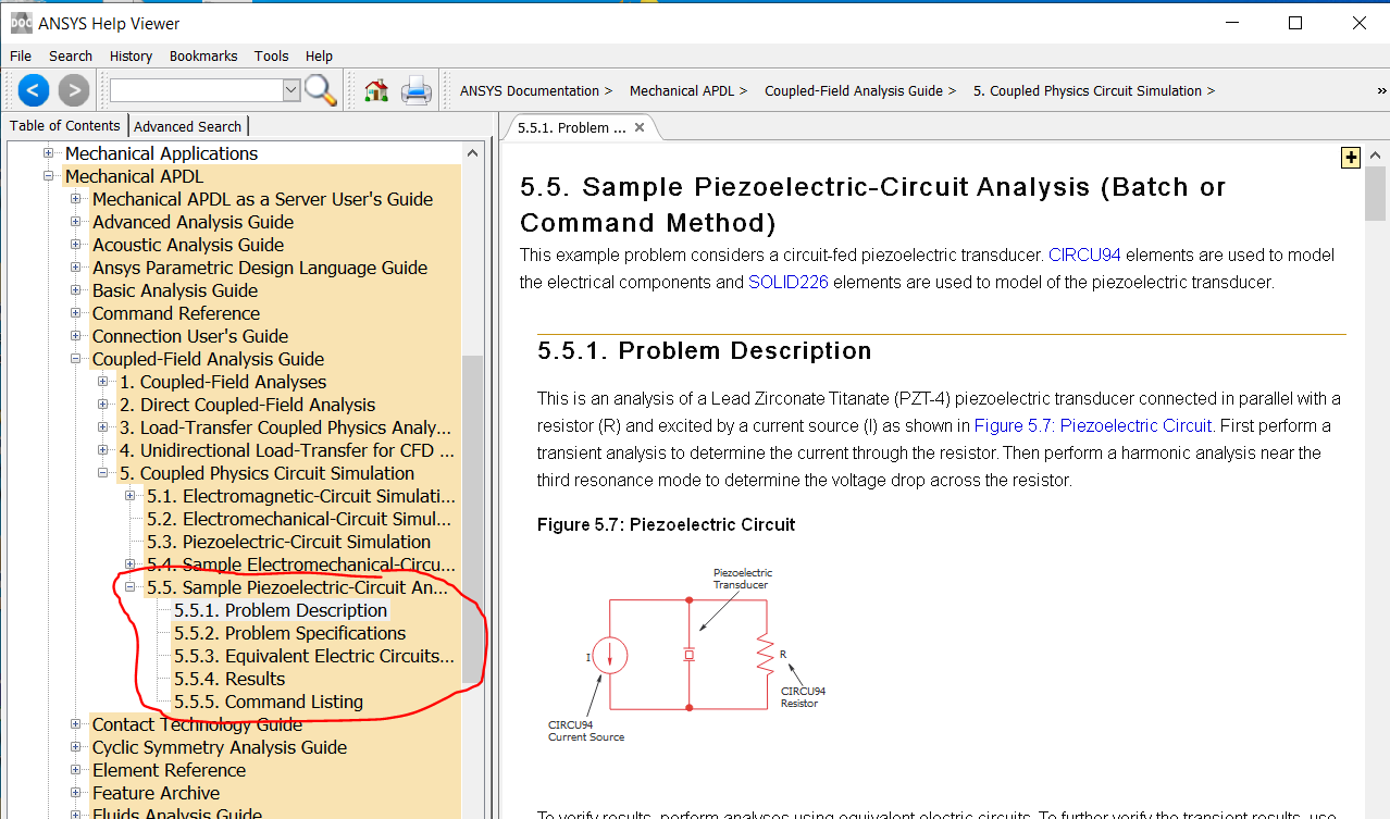
The following is a MAPDL example of a piezo transducer driven by a CIRCU94 independent voltage source and producing acoustic radiation. Post processing is used to verify that total supplied electric power equals total radiated acoustic power. This, of course, isn't exactly what you seek to do, but may nonetheless be helpful.
fini
/cle
/file,test09
/sys,del test09*.png
/vie,1,1,1,1
/cmap
/RGB,INDEX,100,100,100, 0
/RGB,INDEX, 80, 80, 80,13
/RGB,INDEX, 60, 60, 60,14
/RGB,INDEX, 0, 0, 0,15
C********************************************
C*** PARAMETERS
C********************************************
pi=acos(-1)
r_piezo=0.010 ! PIEZO RADIUS
l_piezo=0.005 ! PIEZO LENGTH
r_air=5.0*r_piezo ! RADIUS OF "AIR" DOMAIN IN FRONT OF PIEZO
E=2e11/100 ! ELASTIC MODULUS (ALL STRUCTURAL MEMBERS)
dnsty=1000 ! DENSITY (ALL STRUCTURAL MEMBERS)
nu=0.3 ! POISSON'S
c_air=343 ! AIR ACOUSTIC VELOCITY
dnsty_air=1.2 ! AIR DENSITY
C*** PIEZOELECTRIC PROPERTIES (NOTE: POLED IN Z DIRECTION OF ESYS)
C*** PIEZO DENSITY (kg/m^3)
rho = 7489
C*** PIEZO DIELECTRIC CONSTANTS (PERMITTIVITIES)
ep11 = 3.56e-9/8.854e-12
ep22 = 3.56e-9/8.854e-12
ep33 = 2.92e-9/8.854e-12
C*** PIEZOELECTRIC MATRIX VALUES (C/m^2)
e11 = 0$e12 = 0$e13 = -4.1
e21 = 0$e22 = 0$e23 = -4.1
e31 = 0$e32 = 0$e33 = 14.1
e41 = 0$e42 = 0$e43 = 0
e51 = 0$e52 = 10.5$e53 = 0
e61 = 10.5$e62 = 0$e63 = 0
C*** PIEZO ELASTIC MATRIX VALUES (N/m^2)
$c11=13.2e10$
$c21=7.1e10 $c22=13.2e10
$c31=7.3e10 $c32=7.3e10 $c33=11.5e10
$c41=0$c42=0$c43=0$c44=3.0e10
$c51=0$c52=0$c53=0$c54=0$c55=2.6e10
$c61=0$c62=0$c63=0$c64=0$c65=0$c66=2.6e10
thta_sctr=10 ! SECTOR ANGLE
thta_mesh=10 ! ANGLE OF ELEMENT EDGES SWEPT AROUND GLOBAL Y AXIS
dv_thta=thta_sctr/thta_mesh ! # OF MESH DIVISIONS AROUND SECTOR ANGLE
esz1=r_piezo/10 ! 2D PLANAR MESH SIZE
V_piezo=1 ! PIEZO XDCR VOLTAGE AMPLITUDE
lambda=0.5*r_air ! TARGET ACOUSTIC WAVELENGTH
frqncy=c_air/lambda ! CORRESPONDING FREQUENCY
/title,%thta_sctr% DEGREE SECTOR ROTATED ABOUT GLOBAL Y AXIS
C********************************************
C*** 2D GEOMETRY
C********************************************
/prep7
csys,0
k,1,0,-l_piezo
k,2,r_piezo,-l_piezo
k,3,r_piezo,0
k,4,0,0
k,5,r_air
k,6,0,r_air
asel,none
a,1,2,3,4
cm,piezo_a,area
asel,none
csys,1
a,4,3,5,6
cm,air_a,area
cmse,all
cmpl
C********************************************
C*** MESH 2D GEOMETRY
C********************************************
et,200,200,7
esiz,esz1
ames,all
eplo
C********************************************
C*** 3D ATTRIBUTES AND GLOBAL Y AXIS SWEEP/MESH
C********************************************
C*** PIEZO ATTTRIBUTES
wpcs,-1,5 ! ALIGN WP WITH CYLINDRICAL CSYS,5
cswp,11,0 ! CREATE LOCAL CYLINDRICAL CSYS,11 ALIGNED w/WP (TO SERVE AS PIEZO ESYS)
et,1,226,1001 ! PIEZO SUBSTRATE
C*** MATERIAL ID NUMBER
mnum = 1
C*** ASSIGN VALUES DEFINED IN PARAMETERS
mp,perx,mnum,ep11
mp,pery,mnum,ep22
mp,perz,mnum,ep33
tb,piez,mnum,,18
tbda,1,e11,e12,e13,e21,e22,e23
tbda,7,e31,e32,e33,e41,e42,e43
tbda,13,e51,e52,e53,e61,e62,e63
tb,elas,mnum,,21,aels
tbda,1,c11,c21,c31,c41,c51,c61
tbda,7,c22,c32,c42,c52,c62,c33
tbda,13,c43,c53,c63,c44,c54,c64
tbda,19,c55,c65,c66
mp,dens,mnum,rho
C*** AIR ATTRIBUTES
et,2,220,0 !2
mp,sonc,2,c_air
mp,dens,2,dnsty_air
et,3,130,2
mp,sonc,3,c_air
mp,dens,3,dnsty_air
r,3,r_air,0,0,0
exto,esiz,dv_thta
cmse,s,piezo_a ! CREATE PIEZO ELEMENTS
type,1
mat,1
esys,11
vrot,all,,,,,,4,6,thta_sctr
cmse,s,air_a ! CREATE ACOUSTIC ELEMENTS
type,2
mat,2
vrot,all,,,,,,4,6,thta_sctr
alls
numm,node,1e-8,1e-8
numm,kp,1e-8,1e-8
wpcs,-1,0 ! CREATE INFINITE ACOUSTIC ELEMENTS
wpro,,-90
cswp,13,2
nsel,s,loc,x,kx(6)
type,3
mat,3
real,3
esurf
C***********************************************************************
C*** CIRCUIT IVS (INDEPENDENT VOLTAGE SOURCE) ELEMENT
C***********************************************************************
et,4,94,4 ! CIRCU94 IVS
r,4,V_piezo ! TERMINAL VOLTAGE
alls
*get,nmax,node,,num,max
csys
n,nmax+1,-r_piezo,-l_piezo/2
type,4
real,4
rmod,4,15,r_piezo/2
e,node(0,-l_piezo,0),node(0,0,0),nmax+1
esel,s,type,,1
nsle
nsel,r,loc,y
cp,next,volt,all
alls
eplo
alls
acle,all
etde,200
C********************************************
C*** BCs
C********************************************
csys,5
alls
nrot,all
nsel,s,loc,y ! SYMMETRY PLANES
d,all,uy
nsel,s,loc,y,thta_sctr
d,all,uy
nsel,s,loc,x ! CENTERLINE
d,all,ux
d,all,uy
nsel,s,loc,z,-l_piezo ! BOTTOM OF PIEZO
!d,all,ux
!d,all,uy
d,all,uz
d,all,volt
csys,2 ! EQUIVALENT SOURCE SURFACES
nsel,s,loc,x,r_air
esln
esel,r,ename,,220
sf,all,mxwf
fini
C********************************************
C*** POST PROCESSING TOOLBAR BUTTONS
C********************************************
*cre,pl_pres,mac
fini
/post1
set,1,1,,real
plns,pres
*end
*cre,pl_spl,mac
fini
/post1
set,,,,ampl
plns,spl
*end
*cre,pl_far,mac
fini
/post1
*ask,radius,far field distance,1
phi1=0 ! PHI: X AXIS TO Y AXIS
phi2=180
nphi=72
thta1=90 ! THETA: Z AXIS TO XY PLANE
thta2=90
nthta=0
hfang
hfsy
sound_power_reference=1e-12
ref_rms_pressure=2e-5
set,1,1,,real
*if,thta_sctr,lt,90,then
plfar,prot,splp,phi1,phi2,nphi,thta1,thta2,nthta,radius,ref_rms_pressure,thta_sctr
*elseif,thta_sctr,eq,90,then
hfsym,0,shb,,shb
plfar,pres,splp,phi1,phi2,nphi,thta1,thta2,nthta,radius,ref_rms_pressure
*endif
*end
*cre,P_net,mac
fini
/post1
set,1,1
esel,s,ename,,94
etab,P_elec,nmisc,1
*get,P_elec,elem,elnext(0),etab,P_elec
P_elec=abs(P_elec*(360/thta_sctr)) ! ACCOUNT FOR SYMMETRY - POWER FOR FULL 360 DEG SYSTEM
alls
sound_power_reference=1e-12
hfsym
hfang
prfar,prot,pwl,,,,,,,,sound_power_reference,thta_sctr
*get,p_acoustic_db,acus,,pwl
p_acoustic=sound_power_reference*(10**(p_acoustic_db/10))
/ann,dele
/tla,-0.25,0.825,RADIATED SOUND POWER = %p_acoustic_db% dB
/tla,-0.25,0.775,RADIATED SOUND POWER = %p_acoustic% W
/tla,-0.25,0.725,SUPPLIED ELECTRIC POWER = %p_elec% W
pl_pres
*end
*abbr,pl_pres,pl_pres
*abbr,pl_spl,pl_spl
*abbr,pl_far,pl_far
*abbr,p_net,p_net
*abbr,an_harm,anharm,24,0.1
abbs
abbr
C********************************************
C*** SOLVE
C********************************************
/solu
alls
anty,harm
harf,frqncy
alls
solv
fini
/sys,del *.emat
/sys,del *.esav
/sys,del *.full
eplo
/sho,png,rev $eplot $/sho,close $/wait,2
/post1
P_net
/eof
Best regards
Bill
December 7, 2021 at 11:24 amSubscriberThnak you so much for your response. I am not really sure if I have to consider another capacitance or resistance? Because already the capacitance of the pzt disk is considered in my model by defining the permitiity coefficients (I guess). One of the main problems is that when I apply a load by step function, the voltage signal exactly has a step function shape. However, in our experimental tests the voltage is like this:
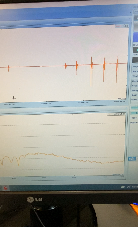 The voltage quickly drops back to zero and it goes from positive to negative value. My voltage amplitude matches well with the open circuit voltage but how to make it like the experiment I don't know.
I appreciate any further suggestion.
Best Ali
December 7, 2021 at 11:24 amSubscriberThnak you so much for your response. I am not really sure if I have to consider another capacitance or resistance? Because already the capacitance of the pzt disk is considered in my model by defining the permitiity coefficients (I guess). One of the main problems is that when I apply a load by step function, the voltage signal exactly has a step function shape. However, in our experimental tests the voltage is like this:
The voltage quickly drops back to zero and it goes from positive to the negative value. My voltage amplitude matches well with the open-circuit voltage but I don't know how to include the sudden discharge and variation from positive to negative.
December 8, 2021 at 2:14 amAnsys EmployeeIf, upon the application of a time varying mechanical load, the measured piezo voltage oscillates and decays to zero before the applied mechanical load ends, then my guess is there must be other passive circuit elements connected to the piezo electrodes. Maybe there's some complex electrical impedance associated with the oscilloscope? Are you saying that a charge amplifier such as the one in the circuit diagram IS connected across the piezo terminals? If so, did you make an attempt to model the circuit to see how it would change calculated results?
There appears to be an Op Amp in the circuit. We don't have an element type to model these but they can be fashioned from a collection of other elements.
Yes, the finite elements comprising the mesh of the piezoelectric device have electric capacitance associated with them.
--Bill
December 15, 2021 at 5:28 pmSubscriberThnak you so much for your response. I am not really sure if I have to consider another capacitance or resistance? Because already the capacitance of the pzt disk is considered in my model by defining the permitiity coefficients (I guess). One of the main problems is that when I apply a load by step function, the voltage signal exactly has a step function shape. However, in our experimental tests the voltage is like this:
The voltage quickly drops back to zero and it goes from positive to negative value. My voltage amplitude matches well with the open circuit voltage but
December 15, 2021 at 5:28 pmSubscriber@wrbukat
Thank you Bill for your response. I tried modeling an additional resistance to the PZT but the voltage didn't change at all. I read a lot about this issue and I found out the problem is the low resistance of the measurement devices in the experiment.
Here is a research paper:

It says if the resistance of the measurement device is too high like G-Ohm, the voltage from the experiment will match the theoretical voltage from the FEA.Or, we have a high voltage amplitude. This means an open circuit condition where we have zero current. But if the resistance is low, the voltage amplitude will be decreased. For that charge amplifier, yes, I am using charge amplifier in my experiment. The most common feature of the charge amplifier and PZT materials is that the generated voltage is just dependent on the feedback capacitance (Cf). So Q=Cf V where V is the voltage in the PZT disk. If I can get same V in my FEA vs experiment my problem is solved. But so far nothing has changed my voltage signal.
It is a difficult step in my research and I don't know how to solve it.
Thank you so much Ali
December 15, 2021 at 5:28 pmSubscriber@wrbukat
Thank you Bill for your response. I tried modeling an additional resistance to the PZT but the voltage didn't change at all. I read a lot about this issue and I found out the problem is the low resistance of the measurement devices in the experiment.
Here is a research paper:
It says if the resistance of the measurement device is too high like G-Ohm, the voltage from the experiment will match the theoretical voltage from the FEA.Or, we have a high voltage amplitude. This means an open circuit condition where we have zero current. But if the resistance is low, the voltage amplitude will be decreased. For that charge amplifier, yes, I am using charge amplifier in my experiment. The most common feature of the charge amplifier and PZT materials is that the generated voltage is just dependent on the feedback capacitance (Cf). So Q=Cf V where V is the voltage in the PZT disk. If I can get same V in my FEA vs experiment my problem is solved. But so far nothing has changed my voltage signal.
It is a difficult step in my research and I don't know how to solve it
Viewing 7 reply threads- The topic ‘How to consider voltage dissipation in modeling piezoelectric force sensors?’ is closed to new replies.
Innovation Space Trending discussions
 Top Contributors
-
peteroznewman
 6515
6515 -
scabo
 1906
1906 -
Dennis Chen
 1463
1463 -
javat33489
 1309
1309 -
Shyam Prasad V Atri
1022
Top Rated Tags
© 2026 Copyright ANSYS, Inc. All rights reserved.
Ansys does not support the usage of unauthorized Ansys software. Please visit www.ansys.com to obtain an official distribution.
-


The Ansys Learning Forum is a public forum. You are prohibited from providing (i) information that is confidential to You, your employer, or any third party, (ii) Personal Data or individually identifiable health information, (iii) any information that is U.S. Government Classified, Controlled Unclassified Information, International Traffic in Arms Regulators (ITAR) or Export Administration Regulators (EAR) controlled or otherwise have been determined by the United States Government or by a foreign government to require protection against unauthorized disclosure for reasons of national security, or (iv) topics or information restricted by the People's Republic of China data protection and privacy laws.

 You are navigating away from the AIS Discovery experience