Ansys Assistant will be unavailable on the Learning Forum starting January 30. An upgraded version is coming soon. We apologize for any inconvenience and appreciate your patience. Stay tuned for updates.
General Mechanical

General Mechanical

Topics related to Mechanical Enterprise, Motion, Additive Print and more.

How to apply fluid pressure on surfaces using apdl code in multistep analysis?

    • fan134
      Subscriber

      Dear Altruists,

      The cube is a rock body, the hole at the middle is a wellbore and the cylindrical body inside the wellbore is a casing. I want to apply fluid pressure at three surfaces: 1) inner surface of the wellbore 2) inner surface of the casing and 3) outer surface of the casing using the following code:

      esel,s,TYPE,,VMIN

      sfe,all,,pres,1,7.58e6

      allsel


      esel,s,TYPE,,VMIN

      sfe,all,,pres,1,7.58e6

      allsel


      esel,s,TYPE,,VMIN

      sfe,all,,pres,1,7.58e6

      allsel


      What should be the value of VMIN? Is it the surface ID's on which I want to apply the fluid pressure?

      N.B.: I tried to extract surface ID from the worksheet but I was unable to do so because it was deactivated even after solving with some random value of VMIN. Can anybody tell me why is it grey even after solution?

      Thanks in advance.

    • mjmiddle
      Ansys Employee

      The images show you are working in workbench Mechanical. Why are you not just inserting a pressure object in the Outline? It handles the APDL commands. You can do that just to check in the ds.dat to see what APDL commands it writes. Select the analysis branch, and press "Environment > Write Input File" to write the APDL input file.

      Please see the documentation for the ESEL command:

      https://ansyshelp.ansys.com/account/secured?returnurl=/Views/Secured/corp/v232/en/ans_cmd/Hlp_C_ESEL.html

      If you choose the ESEL item=TYPE, the documentation reads "Element type number" so that is what you use for VMIN and optionally VMAX. The Element type number is what gets assigned by the ET command. If you were selecting volume elements of a body, that would be all you need to do. but for applying a pressure on a face, there are no surface elements by default. If you look at the ds.dat after using a pressure load with the default options, you'll see it creates surface elements first. The pressure load shows you can select "Applied by" as "Surface effect" (default) or "Direct."

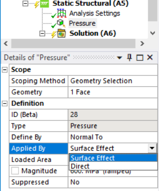
      The "Surface effect" option creates the surface elements to apply the pressure load.

      Also, it's best to communicate workbench selections with APDL by named selections. So select the faces as the named selection "faces_for_press," for example. Then you can select in APDL by CMSEL,S,FACES_FOR_PRESS. Named selections of vertices, edges, faces will be nodal components in APDL. Mechanical creates the pressure load using SF (NSLE first), but it seems you want to use SFE. Doing this fully by APDL would look like this:

      /prep7
      *get,maxet,etyp,0,num,max  ! Find maximum ID of element types
      maxet = maxet + 1          ! Adding 1 to etype ID ensures it is an unused ID
      cmsel,s,FACES_FOR_PRESS    ! Selects nodal component FACES_FOR_PRESS
      et,maxet,154
      keyopt,maxet,2,0
      type,maxet
      esurf                      ! Create surf154 elements on top of volume element faces
      esel,s,type,,maxet
      sfe,all,1,pres,,7.58e6
      allsel
      /solu

      This would go in a command snippet under the analysis branch. You should make sure to use the right keyopts and face number for the SURF154 elements and SFE commands. You should see the documentation for SURF154 in the element reference and SFE in the command reference:

      https://ansyshelp.ansys.com/account/secured?returnurl=/Views/Secured/corp/v232/en/ans_elem/Hlp_E_SURF154.html
      https://ansyshelp.ansys.com/account/secured?returnurl=/Views/Secured/corp/v232/en/ans_cmd/Hlp_C_SFE.html

    • mjmiddle
      Ansys Employee

      The ESYS for the surf154 elements will point outward from the volume mesh and positive values of pressure point in the -Z direction, which is into the volume mesh.

    • fan134
      Subscriber

      Thank you so much for your response. After applying the pressure, I'm getting deformation in the wellbore. But this shouldn't be the case because there won't be any kind of deformation in the wellbore. I tried to fix this by setting the displacement in the wellbore as 0. But, in that case, I was getting fixed stress distribution everwhere. Can you suggest me something? or is it possible for you to take a look at my model? Thanks in advance.

    • fan134
      Subscriber

      To let you know, my model has the following steps:

      Step 1. The model is loaded with horizontal and vertical in-situ stresses.

      Step 2. The borehole is drilled, and a fluid weight is applied to the rock formation.

      Step 3. The casing is added to the borehole.

      Step 4. Fluid weight is applied to the inner and outer surfaces of the casing and the borehole.

    • mjmiddle
      Ansys Employee

      You orginally said you wanted to apply pressure to the inner surface of the wellbore as well as inner and outer surface of the casing. A pressure load is going to cause deformation in the real world, even if the material is very stiff, in which case the deformation would be very small. But the material must be free to deform if a pressure load is to make sense. Applying a pressure and a normal/radial displacement to the nodes is contradictory. It will probably ignore the pressure since a displacement is a direct degree-of-freedom load/support. If you are saying the material is so stiff that the pressure effect is negligible, then you are making an engineering assumption, and there's no need applying the pressure to the inner wellbore face. You might as well use a rigid body there depending on what you expect on other boundaries of that body, or not even include that body in your model.

      Also the image shows the mesh is much too coarse on the wellbore and casing faces for an accurate result. Make smaller elements there. Also make sure to check the result with a scaling factor of 1 as a sanity check.

      We cannot send files over the forum. Forum posts are intended for simpler questions, and those questions applicable to a wide audience, not for a specific model. If you want to send the model for review, please submit a support case on the Ansys Customer Portal.

Viewing 5 reply threads
  • The topic ‘How to apply fluid pressure on surfaces using apdl code in multistep analysis?’ is closed to new replies.
[bingo_chatbox]