Ansys Assistant will be unavailable on the Learning Forum starting January 30. An upgraded version is coming soon. We apologize for any inconvenience and appreciate your patience. Stay tuned for updates.
Electronics

Electronics

Topics related to HFSS, Maxwell, SIwave, Icepak, Electronics Enterprise and more.

[HFSS] Analysis of Feed Horn Radiation Pattern Changes with Offset Reflectors

    • shkim
      Subscriber

      When the radiation pattern of the feed horn (1.12 GHz) is analyzed using the HFSS-IE Hybrid Solver with the feed horn placed inside a box for FEA and two absorbing panels (Impedance Boundary) installed in front of it, the following result is obtained. However, when aluminum offset parabola dual reflectors are added, the feed horn's radiation pattern changes as shown. I would like to know the reason why the feed horn's radiation pattern changes, even though it should remain unchanged.

      Before adding reflectors :

      After adding reflectors :

      image.png</p>

      Reflector Setup Information: Finite Conductivity Boundary,Hybrid Regions(IE Regions)

      • Material: Aluminum 
      • DC Thickness: 10 mm
      • Surface Roughness: 0 (Groiss )
      • Z-axis Reflector Position: 1644.0583 cm from the origin along the Z-axis
      • Y-axis Reflector Position: -451.17 cm along the Y-axis and -922.24 cm along the Z-axis from the origin
      • Distance Between Reflectors (Center-to-Center): 1026.68 cm (38.32λ at 1.12 GHz)
      • Angle Between Reflectors: 26.06855°

      Adaptive Solution Settings:

      • Frequency: 1.12 GHz (Single Frequency)
      • Maximum Delta S: 0.05 (Convergence Criterion)
      • Maximum Number of Passes: 5
      • IE Solver Setting업로드한 이미지

      I would appreciate guidance on the following points:

      • What are the common factors that could cause a feed horn's radiation pattern to change upon the addition of offset parabola dual reflectors?

      • Are there specific aspects of the reflector design or placement that I should examine to understand this alteration?

      • Could the simulation parameters within HFSS-IE be contributing to this issue, and if so, which settings are most critical to review?

      Any insights or suggestions from those with experience in similar simulations or practical implementations would be highly valuable.

    • Praneeth
      Ansys Employee

      Hi,

      Thank you for reaching out to the Ansys learning forum.

      Please share more details of your setup to help us serve you better, like:

      1. How is the region around the feed horn antenna is defined?
      2. Are you using any boundary to the walls of the feed antenna surrounding region?
      3. Why do you think the radiation pattern does not change when reflectors are placed in the main beam direction of the feed-horn?

      Also please share any other details that can help us identify your setup more accurately.

      You can also go though  "open example > HFSS > Antennas > Parabolic Dish or Gregorian Reflector" models to understand the setup with reflectors.

      Best regards,
      Praneeth.
      Click here to join Electronics Community and build a network.

    • shkim
      Subscriber


      Hi Praneeth,

      Thank you for your response and suggestions. Here are additional details regarding my setup:

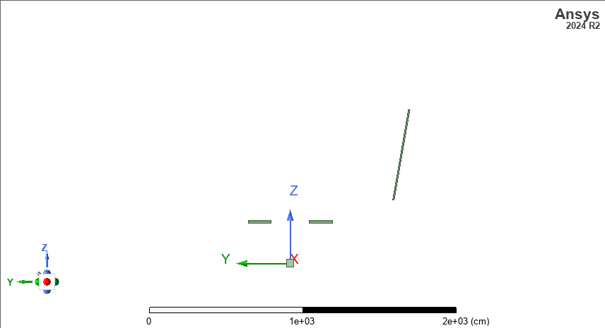
      1. Vacuum box and feed horn definition:

       A vacuum box was defined around the feed horn.

       The feed horn is set up using the FEBI (Finite Element Boundary Integral) method.

      2. Absorbing boundaries:

       In front of the vacuum box, two walls simulating absorbers were placed. These absorbers effectively minimize unwanted reflections, and they are working well in the simulation.

       The absorbing walls are configured as an impedance boundary with resistance of 300 ohm and reflectivity of 0.01.

       The absorbing walls are part of a rectangular box, which is also set up using the FEBI method.

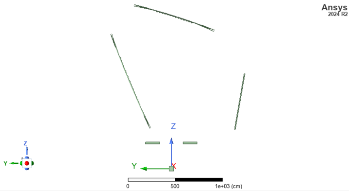
      3. Reflector system setup:

       Two reflectors were placed to simulate an offset Gregorian dual-reflector system.

       The feed horn was positioned at the focal point of the reflector system.

       The radiation from the feed horn first hits the small (sub) reflector, then reflects onto the larger main reflector.

       There was no returned signal detected on the feed horn, confirming that the absorber setup is functioning as expected.

      4. Next steps:

       I will try the example you suggested (HFSS > Antennas > Parabolic Dish or Gregorian Reflector) to compare results.

       If needed, I can send my model for further review to better understand the cause of the radiation pattern changes.


      Let me know if you need any additional details.


    • Praneeth
      Ansys Employee

      Hi,

      Thank you for the reply.

      Please confirm whether you are assigning any hybrid region to the reflectors. If so, the radiation pattern would definitely change between the reflector and no reflector designs.

      Best regards,
      Praneeth. 

Viewing 3 reply threads
  • You must be logged in to reply to this topic.
[bingo_chatbox]