TAGGED: eigenmode, energy-error, fields-calculator, integration
-
-
September 9, 2021 at 9:57 pm
hiuyung.wong
SubscriberI set the energy in eigenmode simulation (Fields=>Edit Sources) to be 1J. Then I integrate the simulation domain on 1/2(eps|E|^2+mu|H|^2). And I got exactly 2J. I have made sure I use the correct E and H. Is this expected? Why it is 2X larger than the assumed energy? Thanks!
September 13, 2021 at 12:31 pmPraneeth Munaga
Ansys Employee
Please let us know more details about your simulation model to help us serve you better.
Best regards.
September 14, 2021 at 3:54 pmjdmac
Subscriber@hywong2 Sounds like half your energy is stored in E and half in H.I would assume the discrepancy arises because HFSS is normalizing your eigenmodes to energy stored in the E-fields only.Thus, quantity (eps_rel*eps_0/2 * int_volume ( E dot E*) dV ) should yield 1.0J.You'll want to account for this if you use a different convention.
September 14, 2021 at 7:37 pmjdmac
SubscriberActually, here's a clearer answer: This is the difference between energy stored over a complete wave cycle vs. instantaneous energy. If you're going to do 1/2(eps|E|^2 + mu|H|^2), then you need to take the Real component of each E and H term before your dot product. You can use the AtPhase function (from the Complex drop down menu) to specify which phase you're evaluating fields at.
Scl : Integrate(Volume(AllObjects), Dot(AtPhase(, 90), AtPhase( , 90)))
Otherwise, if you just do E . E* + H . H*, then you're double booking the energy.
Here's a graphic I made to explain it:

September 16, 2021 at 6:39 pmhiuyung.wong
SubscriberThank you very much! I tried what you said but the result is strange. I got about 0.002J when integrate H (instead of 1J) and 1.998J when integrate E (instead of 1J). But I realized that this is because I have a lumped RLC boundary condition with ~10nH inductor. If I make it very small (e.g. 10fH), then I get 1J in both integration (same as yours). Any idea why adding a lumped inductor will cause this issue? Thanks!
September 16, 2021 at 8:43 pmjdmac
SubscriberFascinating. I don't know the answer to that one. I assume your H field is not 0. I wonder if the Lumped RLC causes H to cancel out when you integrate over the whole domain? I think the lumped RLCs work by applying a current, so I guess that's possible. It sounds like energy gets redirected into E, thus satisfying conservation of energy. Interesting. I'm not sure if that's physical or a quirk of the lumped RLC element. I suspect it's the latter, since a physical inductor works by storing energy in magnetic fields. If I were you, I'd plot an animation over time of J on that lumped RLC. And also look at a 3D plot of H. Maybe someone else will know why this is.
September 17, 2021 at 1:04 amhiuyung.wong
SubscriberIt is right that the energy goes to the inductor. The only thing puzzling me is that energy in E is integrated to be about 2J and energy integrated in H + energy in the inductor is also about 2J. If I set the eigenmode energy to 0.5J, they both scale accordingly (reduced by half). If the extra energy is due to the current applied as you said, looks like it is using the same setting in the eigenmode energy. Just to share what I observe. Thanks!
September 21, 2021 at 2:21 pmjdmac
SubscriberYeah, I'm not sure what's going on here, but it's definitely non-physical.
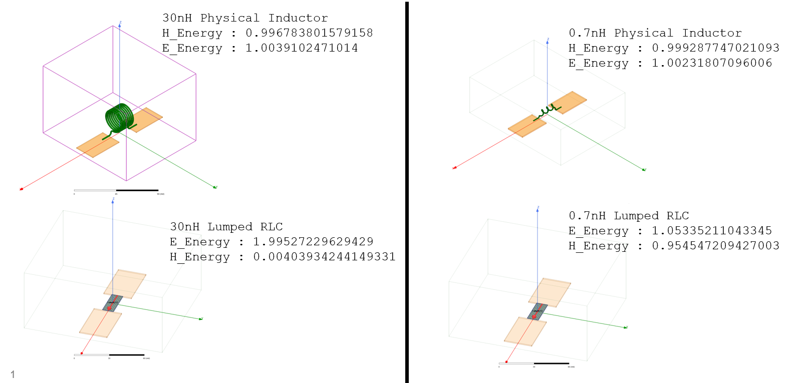
Plainly, when you compare LumpedRLC inductors with physical inductors, for the physical version, energy stays balanced between E and H, whereas for the LumpedRLC inductor version, energy gets transferred entirely to E as the inductance value grows. There is some quirk of the currents applied to make the Lumped RLC boundary condition happen that radically alters where energy is stored. The thing you have discovered makes me distrust Lumped RLCs for eigenmode problems.
September 28, 2021 at 3:15 pmCarlos Mulero Hernandez
Ansys Employee@hywong2
The formula you have used is correct for RMS phasors.HFSS field quantities are peak phasors.When using peak phasors, the time-average electric and magnetic stored energy are volume integrals of ┬╝(eps)E^2 and ┬╝(mu)H^2. This provides the missing factor for your field expression.
Information on the field quantity phasors in electronics desktop 2021R2 can be found under:
HFSS Help > HFSS Technical Notes > The HFSS Solution Process > Field Solutions > Peak Versus RMS Phasors
https://ansyshelp.ansys.com/account/secured?returnurl=/Views/Secured/Electronics/v212/en/home.htm%23../Subsystems/HFSS/Content/HFSS/PeakVersusRMSPhasors.htm%3FTocPath%3DHFSS%7CHFSS%2520Help%7CHFSS%2520Technical%2520Notes%7CThe%2520HFSS%2520Solution%2520Process%7CField%2520Solutions%7C_____4
A reference to the expressions for time-average stored energies is Table 1-6 in BalanisÔÇÖ Advanced Engineering Electromagnetics, 2nd ed.


Viewing 8 reply threads- The topic ‘Energy in Eigenmode’ is closed to new replies.
Innovation SpaceTrending discussionsTop Contributors-
6420
-
1906
-
1457
-
1308
-
1022
Top Rated Tags© 2026 Copyright ANSYS, Inc. All rights reserved.
Ansys does not support the usage of unauthorized Ansys software. Please visit www.ansys.com to obtain an official distribution.
-