Ansys Assistant will be unavailable on the Learning Forum starting January 30. An upgraded version is coming soon. We apologize for any inconvenience and appreciate your patience. Stay tuned for updates.
Electronics

Electronics

Topics related to HFSS, Maxwell, SIwave, Icepak, Electronics Enterprise and more.

Electromagnetic simulation of material with an alloy

    • Rajkumar Varaganti
      Subscriber

      Hello there,


      I am trying to perform an electromagnetic simulation in Ansys Maxwell. In my case, I have a rectangular plate made up of Aluminium and I want to add small MnB (Manganese Boron) particles to this plate. For this reason, I have made a small sphere and assigned the necessary material properties. The small particles were placed inside the rectangular plate. But when I try to run the simulation I get an error message as: two parts intersect with each other. How do I add MnB to the rectangular plate made up of Aluminium? Is it even possible to do that in Ansys Maxwell?
      If not Maxwell, any other module of ansys where I can do this? Later I can import the model into maxwell


      Thanks in advance.


      Regards,


      Rajkumar

    • NKC
      Forum Moderator

      Hi,

      Since the MnB spheres are placed inside the plate. You need to use the subtract operation.

      Select all the spheres and rectangle > select subtract operation from Draw menu 

      On the popup menu add all the spheres to tool and plate to blank side.

      * Select clone tool objects before operation.

      This should eliminate the objects intersecting error.


      Regards

      Navya

    • Rajkumar Varaganti
      Subscriber

      Thank you for your reply.  I was able to create the above mentioned model successfully. Now, I need to see the effect of MnB on Al in presence of electro-magnetic field. I have determined the ohmic losses and coupled the solution with steady-state thermal module to visualize the temperature distribution near the MnB particles. But, I cannot see any effect of the particles and the load imported (ohmic losses) from Maxwell is very low to see any effect. As a result, I could not see any effect of these particles. Why there is a loss of imported load from Maxwell to steady-state thermal. How can I prevent these losses during the coupling of two modules?

    • AndyJP
      Subscriber

      don't forget to set "solve inside" flag for metal parts. HFSS cuts angles by not solving good conductors in 3D. It just analyzes the skin depth, but ignores everything below the surface.   

    • Rajkumar Varaganti
      Subscriber
      .

      From the figure you could see both the normal view and sectional view. I have a Al plate and inside this plate I have MnB spheres. I would like to transfer the heat from the spheres to the plate. I have tried various boundary conditions, but couldn't find the correct one in my case. As there are two different materials, how could we make a thermal contact so that we could see the temperature gradients?

      .
    • Karthik Remella
      Administrator
      Hi,
      Do you have any contacts in your model? Are you sure that these contacts are set-up correctly in your thermal model?
      Also, what are your boundary conditions and how are you setting them up?
      Could you please share some screenshots so we can understand your issue better?
      Thank you.
      Karthik
    • Rajkumar Varaganti
      Subscriber
      .

      Hi Karthik,

      Thank you for your reply.

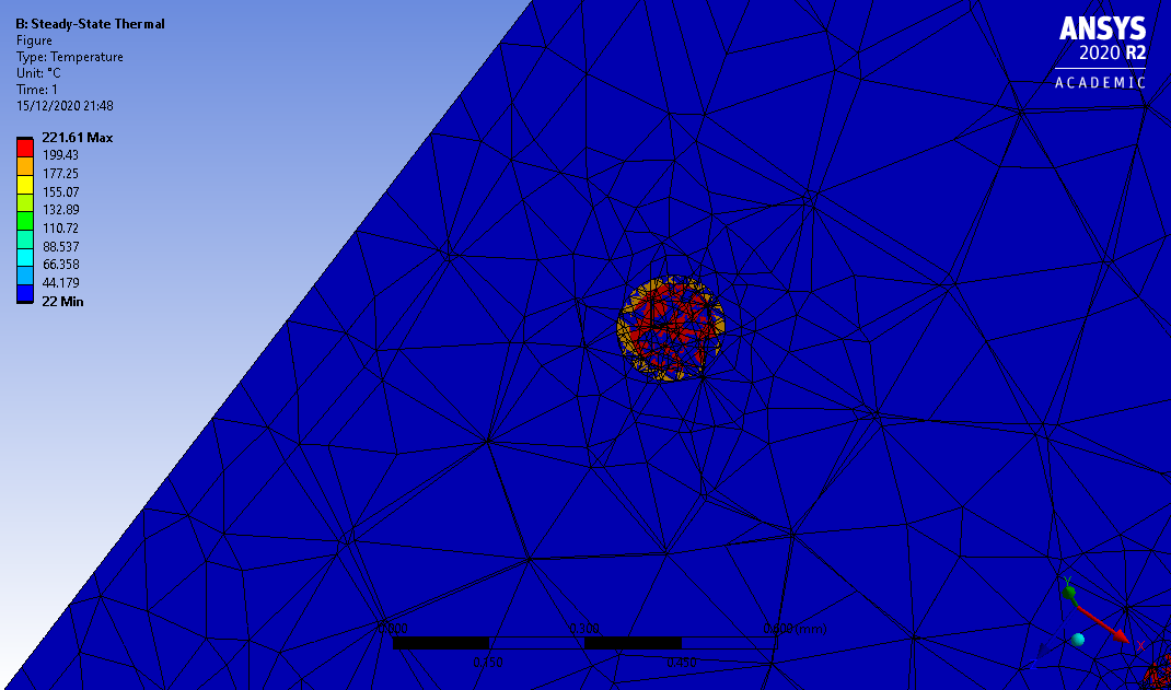
      The simulation results which you see in the figures are obtained by coupling with maxwell. The ohmic losses from the maxwell serves as an input to the setup of steady-state thermal. Now when I import the load for the plate and the spheres, I don't get the exact losses as observed in maxwell.

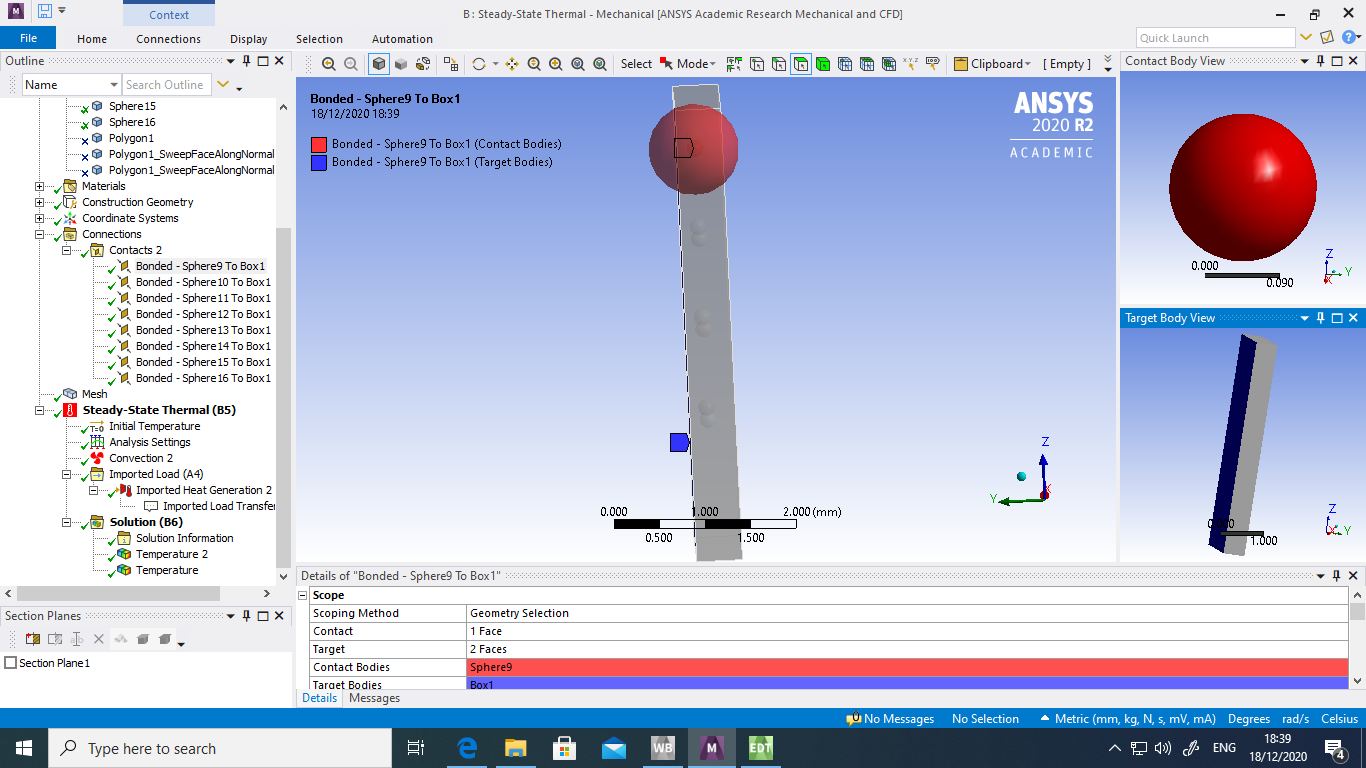
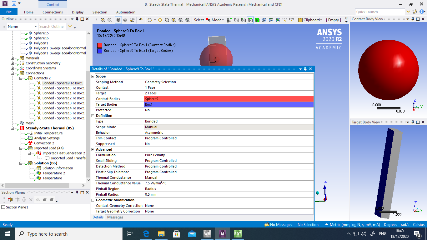
      Regarding the boundary conditions, in maxwell the simulation didn't run as it was intersecting the inside of the plate. For this reason, the spheres are located inside the plate without touching any faces inside. Now when it comes to steady-state thermal, as these spheres and plate don't have any relation they were made as bonded contact. Convection was used for the outside faces of the plate. The problem is after trying all boundary conditions like convection, coupling, ... I couldn't actually find a suitable way by which I could allow the transfer of heat from the spheres to the plate.

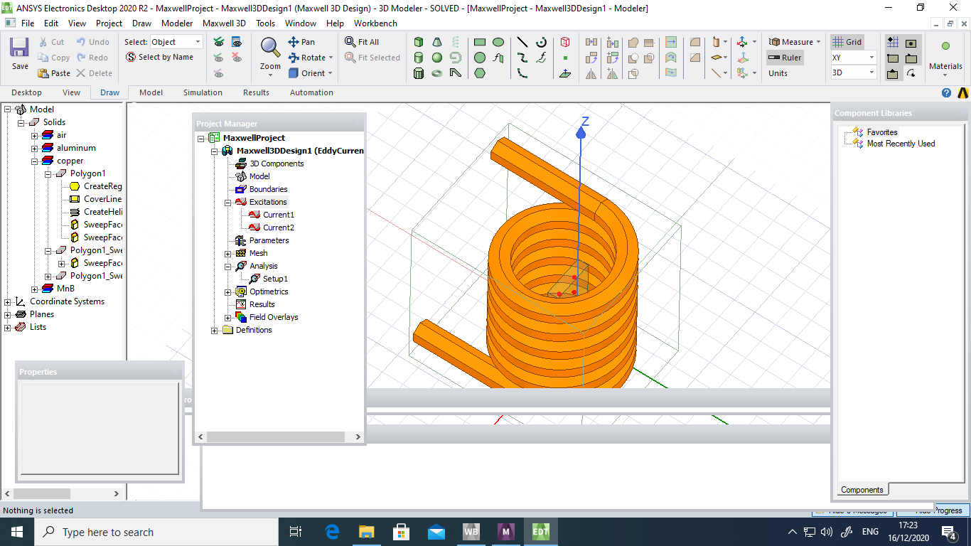
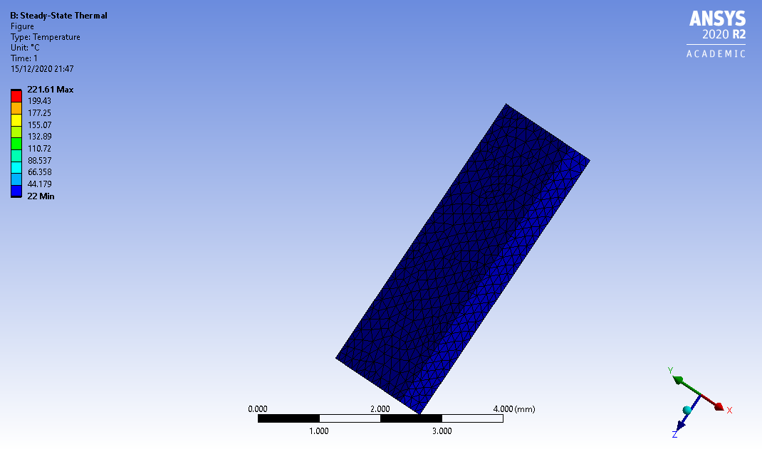
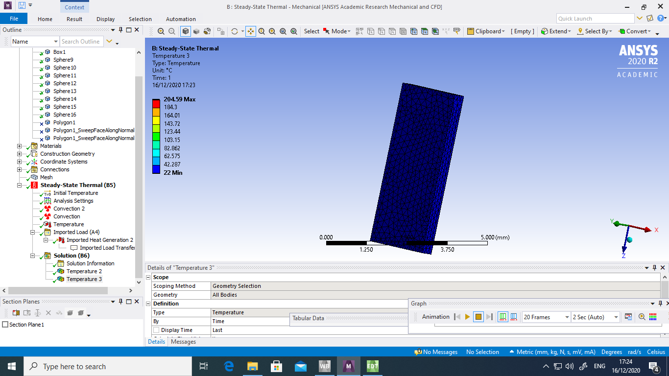
      The first figure shows the model in Maxwell with an coil for induction heating of the plate with spheres inside. The second figure shows the steady-state thermal where the results from maxwell are coupled to import load. Essentially, due to induction heating of the plate, both the plate and spheres undergo different ohmic losses and as a result I would like to plot the temperature of the entire model but with a heat transfer from the spheres to the plate.

      .
    • Rahul Kumbhar
      Ansys Employee
      Hi Array Can you please add some snapshots of bonded contact including both setting as well as transparent geometry ?
    • Rajkumar Varaganti
      Subscriber
      .

      rkumbhar thank you for your reply. Please find the screenshots of the settings used for the contact. I have used the pinball approach to create a thermal contact between the spheres and the faces of the plate. Also, do you know why the ohmic losses are so low for spheres ( in my case the spheres are 0.09mm and when import load from maxwell, the ohmic losses are low) But when I simulate the spheres alone without the plate, I get high ohmic losses)

      .
    • Rahul Kumbhar
      Ansys Employee
      Hi Array The contact doesn't looks good. You have the contact between sphere surface to plate surface. Instead the sphere should be substracted from the plate to create cavity. Then there should be contact defined between sphere surface and cavity surface of the plate.
      You can use large pinball radius to define the contact and all other program controlled options. Also are you selecting all the bodies in imported heat generation object? The overlapping constraints such as convection, imported heat and contact all on the same face can this type of issue. I would suggest first to modify the geometry by substracting the spheres.
    • Rajkumar Varaganti
      Subscriber
      Array Firstly, I don't want to have a cavity in my model as I want to see the effect of these spheres as a result of electro-magnetic simulation in maxwell. Regarding the pinball radius, the imported load was taken only for the spheres as I want see the effect of them. Also, the convection coefficient was used only for the two faces of the plate.
    • Rajkumar Varaganti
      Subscriber
      Array please find the above discussion on my issue. Looking forward to your response
    • peteroznewman
      Subscriber
      Array sorry, I don't have access to Maxwell. I think you should subtract the spheres from the plate to create cavities for the spheres.
    • Rajkumar Varaganti
      Subscriber
      Array thank you for your reply. Whom can I contact regarding this issue in Maxwell? Do you know someone who has access to Maxwell?
    • Rajkumar Varaganti
      Subscriber
      .

      scpowers could you please take a look at my problem. I am dealing with an induction heating poblem. Maybe you could have some idea

      .
    • Rahul Kumbhar
      Ansys Employee
      .

      You have contact between the spheres and faces of the plate. On the same faces of the plate, there is convection boundary condition. So you might not bale to see the proper heat transfer. My suggestion still would be to create cavity in plates around the spheres and have the bonded contact in those places.

      .
Viewing 15 reply threads
  • The topic ‘Electromagnetic simulation of material with an alloy’ is closed to new replies.
[bingo_chatbox]