Hello, I was able to define non-linear material properties for concrete using APDL commands provided by Professor Brock D. Hedegaard as a base in Ansys Mechanical. The parameters are for a "Drucker-Prager Microplane plasticity " model and attached below is the code:
/PREP7
! Step 1: Define elastic properties of material
E = 30000 ! Young's Modulus, MPa
nu = 0.2 ! Poisson's Ratio, unitless
! Step 2: Define microplane model properties
! - Approximations and typical ranges per intuition... your concrete may be different!
fc = 80 ! Uniaxial compressive strength, MPa
fb = 92 ! Biaxial compressive strength, MPa (estimate as 1.15*fc if unknown)
ft = 2 ! Tensile strength, MPa (estimate as 0.1*fc if unknown)
Rt = 1 ! Tension cap hardening constant, unitless (typically = 1)
D = 20e4 ! Compressive hardening constant, MPa^2 (typically between 1e4 and 50e4)
sigma_cv = -32 ! Int. of comp. cap and DP yield, MPa (always negative, approximately -2/3*fb or lower)
Rc = 2 ! Compression cap ratio constant, unitless (typically = 2)
gamma_t = 0 ! Tensile damage threshhold, unitless (typically = 0)
gamma_c = 5e-5 ! Compressive damage threshhold, unitless (typically between 1e-5 to 10e-5)
beta_t = 6000 ! Tension damage evolution, unitless (typically 1.5*beta_c)
beta_c = 4000 ! Compression damage evolution, unitless (typically between 1000 and 10000)
! Step 3: Define nonlocal parameters c and m
c = 650 ! Nonlocal range parameter, mm^2 (element size should be < 0.5*sqrt(c))
m = 2 ! Over-nonlocal parameter, unitless (typically 1 to 3)
! Step 4: Select element type
element = 215 ! Element type number (Linear = 215, Quadratic = 216)
! ===================================================================
! You should not need to change code below this point, unless
! you are debugging, modifying, or otherwise know what you are doing
! ===================================================================
! Assign Elastic Properties
MP,EX,conc,E ! Assign Young's Modulus
MP,NUXY,conc,nu ! Assign Poisson's Ratio
! Assign microplane properties for coupled damaged-plasticity (MPLANE-DPC)
TB,MPLANE,conc,,,DPC
TBDATA,1,fc,fb,ft,Rt,D,sigma_cv
TBDATA,7,Rc,gamma_t,gamma_c,beta_t,beta_c
! Assign nonlocal properties to microplane model (MPLANE-NLOCAL)
TB,MPLANE,conc,,,NLOCAL
TBDATA,1,c,m
! Define coupled elements (this code assumes ITYPE = matid, which it should be in almost all cases)
itype = conc
et,itype,element
keyopt,itype,18,2 ! Element needs 2 nonlocal parameters for keyopt(18)
! Switch element type of those that are assigned Concrete
esel,s,mat,,conc
emodif,all,type,itype
! To check that everything worked out, print the element list
allsel
etlist,all
! Now proceed to the solution and output all results
/SOLU
outres,all,all
-Trying to validate the defined parameters, I modelled a generic beam and subjected it to uniaxial and flexural deflection schemes.
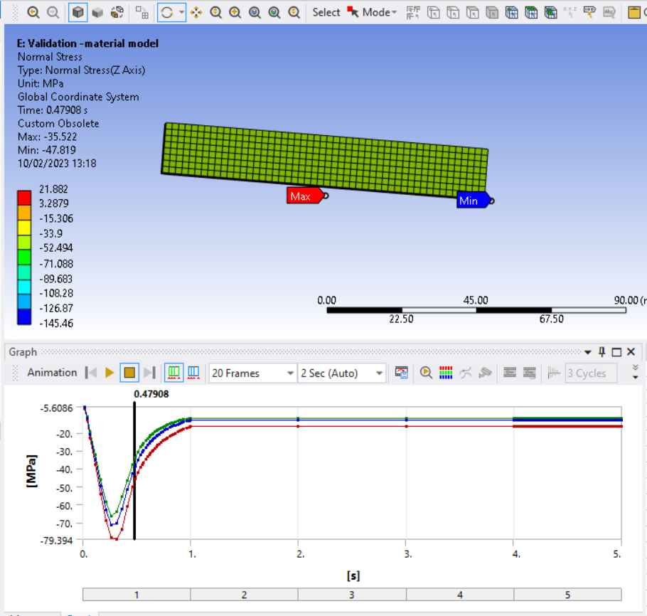
The uniaxial loading conditions gave the expected results, with both compressive and tensile stress values peaking at the defined strength parameters before softening occurred. I have attached images below:
Fig.1 Peak compression
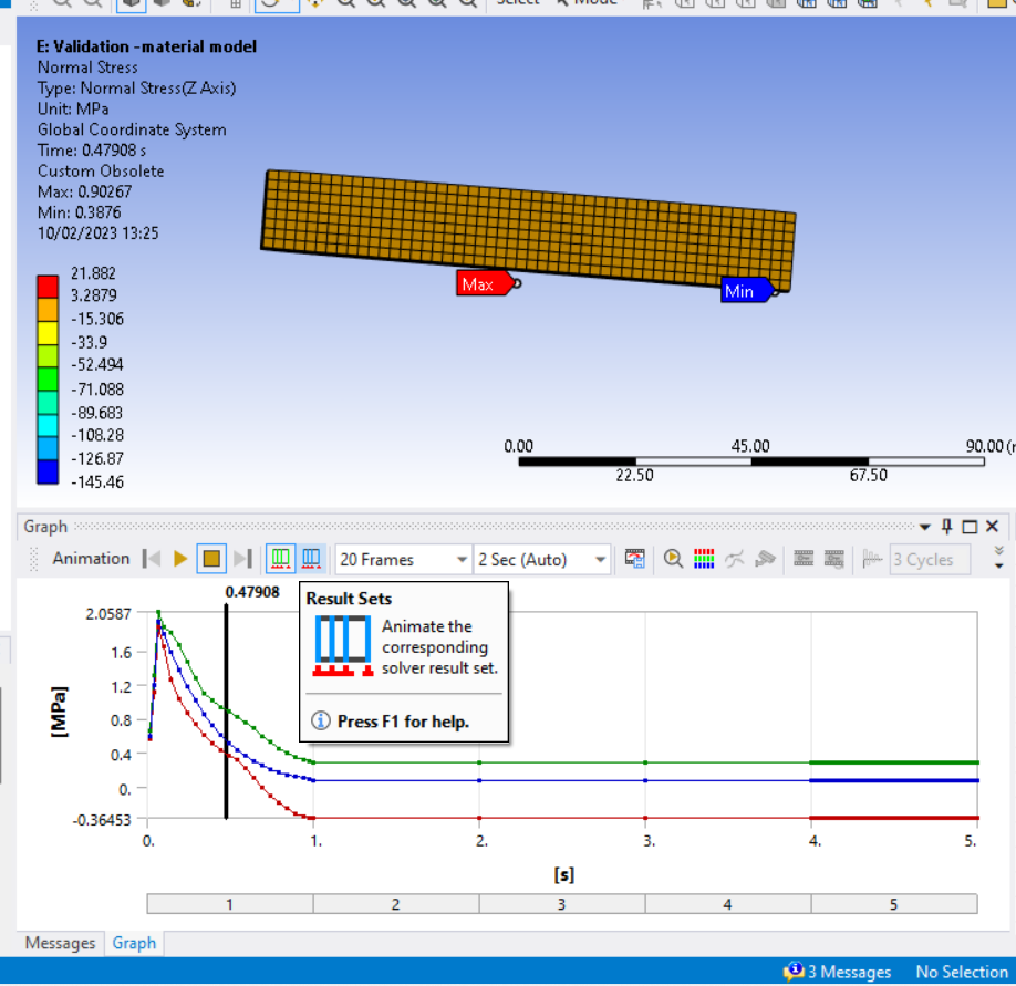
Fig.2 Peak tension
-In contrast, flexural loading conditions give results for peak normal stress which significantly exceed defined parameters, even after varying the applied displacement on the beam.
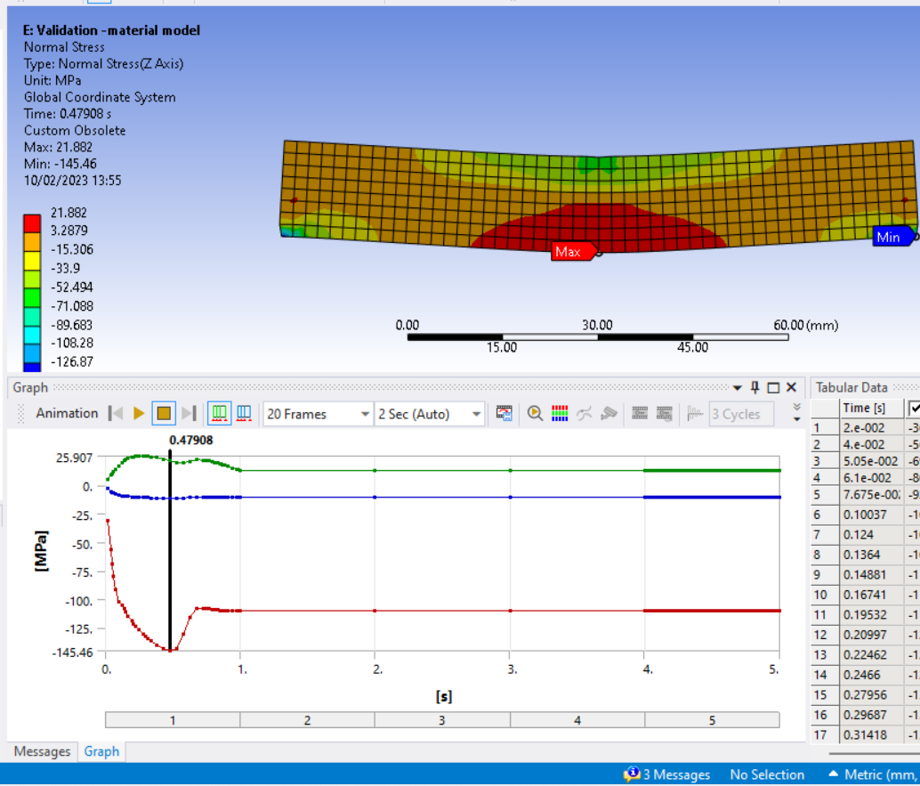
Fig .3 Peak compressive and tensile stresses for the flexural loading condition.
It is my understanding that the normal stress in the z-direction is composed of Tensile and compressive stresses beneath and above the neutral axis respectively. I would appreciate feedback on possible errors in my assumptions or potential reasons for the disparities in results.
Thanks in Advance.