TAGGED: ansys-aqwa, mesh, wind-turbine
-
-
December 30, 2025 at 12:57 am
wsy1366
SubscriberHello everyone,
I'm civil engineering B.S. student in Korea currently interested in Floating Offshore Wind Turbine design.
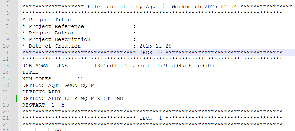
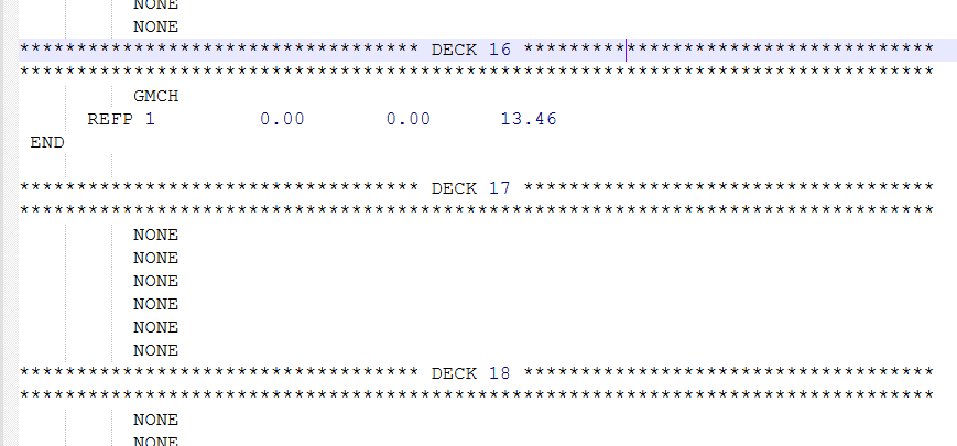
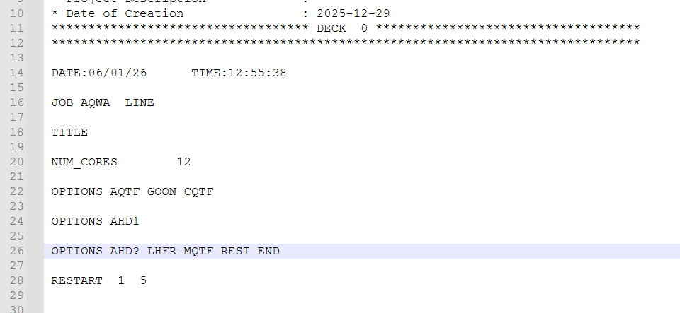
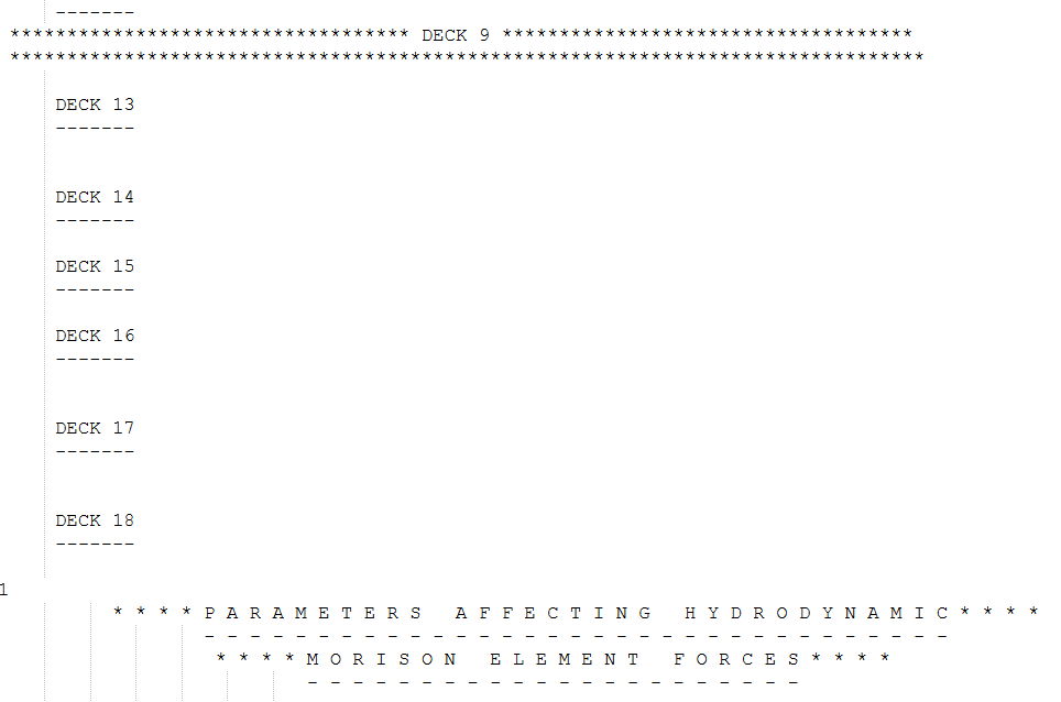
So i'm working on Ansys AQWA program to analyze NREL 5MW Semi-submersible platform.
Due to my insufficient back ground knowledge i've got to some questions about "Thin" and "Line Body".
I understood that "Line Body" as a Morison's element is not included in calculation of potential theory, for example added mass or radiation damping coefficient. (Am I right?)
So i designed lower pontoon and bracing of NREL reference wind turbine as "Line Body" instead of "Thin" because they have relatively small diameter with respect to length itself.
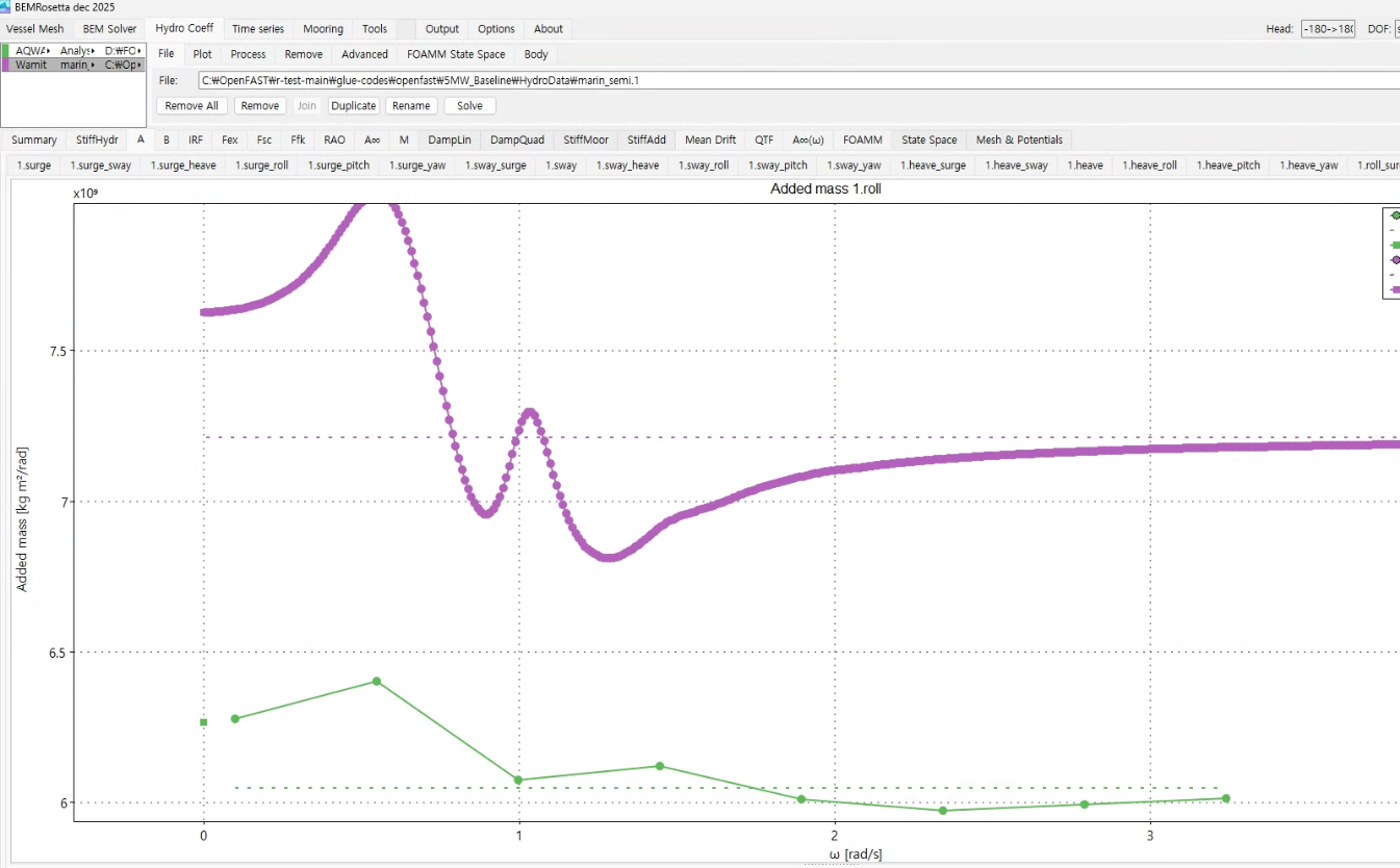
But i found out serious mismatching about heave added mass down below. (Case 01)
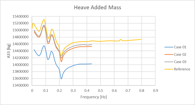
So i desinged lower pontoon as "Thin" (Case 02) and bracing (Case 03) too, so that i could get similar behavior with reference(caculated by WAMIT).
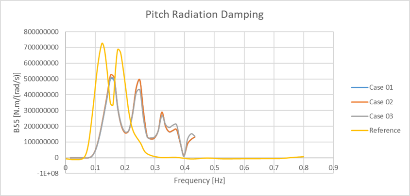
And I also found out that pitch radiation damping does not align with reference.
More over, result of "Froude-Krylov Force" and "Diffraction Force" in pitch, yaw direction of Case 03 has serious discrepancy like down below:
Thus I can't trust heave added mass result for Case 03.
So my question is:
Q1. Why does designing lower pontoon as "Thin" make substantial difference in "heave added mass"?
Q2. How can i deal with "pitch radiation damping" coefficient.
Q3. What is the actual difference between "Line Body" and "Thin"
Q4. Can I use "Case 03" design to match heave added mass?
Thank you all for your help, and have a happy New Year!
-
January 5, 2026 at 9:15 am
wsy1366
Subscriber -
January 5, 2026 at 11:45 am
Mike Pettit
Ansys EmployeeHello,
You are right to use the REFP data record to change the hydrodynamic reference point, but I guess you should be setting the point to [0, 0, 0] rather than [0, 0, 13] if you want results to be output with respect to the mean water level. You will only see the transformed hydrodynamic properties in the Aqwa listing (LIS) file; the graphs will always show properties with respect to the structure COG.
I hope this helps.
Mike
-
January 5, 2026 at 12:46 pm
wsy1366
SubscriberDear Mike,
Thanks for reply.
I changed my Analysis.dat file down below:
But there is no change at all and there is no results about DECK16 on "Analysis.LIS":
(The purple value is from NREL OpenFAST glue code, i set only 7 wave frequencies for quick validation)
I exectued Aqwa.exe and Analysis.dat in CMD not in Workbench.
Is there any other settings or option which i need to turn on or handle?
Thanks in advance:)
-
January 5, 2026 at 2:46 pm
Mike Pettit
Ansys EmployeeHello,
First, please check that the SFBM option is not included in the OPTIONS at the top of the input file. This would disable any geometric changes that are defined in Deck 16 (GMCH). I guess this may be the case, as I would expect to see the REFP input reported under DECK 16.
Once there is no SFBM option in your file, please scroll towards the bottom of the new Analysis.LIS, where you should find a section starting:
* * * * ( C H A N G E O F ) S T R U C T U R E C H A R A C T E R I S T I C S * * * *
Then you will find outputs such as 'TRANSFORMED STIFFNESS MATRIX', 'TRANSFORMED ADDED MASS', 'TRANSFORMED DAMPING' and so on.
Mike
-
January 6, 2026 at 5:38 am
wsy1366
SubscriberDear Mike,
Thank you for kind reply.
As you can see, i deleted "SFBM" option from the text file(Analysis.dat) and executed again.(I wrote down [0, 0, 13.46] because i read that displacement is from original coordinate(C.O.G of structure), AQWA reference manual 25.7)

I found out that there is no "SFBM" option anymore in result text tile(Analysis.LIS):But it doesn't change at all...
I think i'm lost here.
Is there any other options should i handle?Again, Thanks in advance:)
-
- You must be logged in to reply to this topic.
-
4924
-
1613
-
1386
-
1242
-
1021
© 2026 Copyright ANSYS, Inc. All rights reserved.


