-
-
February 20, 2023 at 6:35 am
pradhan.5
SubscriberHi,
I am designing a simple circular coil using a Cylinder (Copper) and UDP's polyhelix coil.
The dimensions are as follows:
Din=140 mm
Dout=280mm
w=1.2446mm
No. of turns= 17
S (dist. b/w turns)= 3mm
The LCR meter provides a value of 75.91 uH but ansys simulation gives a value of 66.8 uH which is highly inaccurate. Even JMAG provides a value of 74.7 uH. Could you comment on why it is so and what might be possible settings that has to be seen. -
February 20, 2023 at 3:47 pm
-
February 21, 2023 at 6:51 am
pradhan.5
SubscriberThanks Navya,
The results did improve but still there is some inaccuracy. Except the mesh settings, what can be other reasons. Could you tell?
-
February 21, 2023 at 10:04 am
Navya Chode
Ansys EmployeeCan you plot the B fields on a cross-section plane of your model and share the screenshot?
Also, share the screenshot of your solution setup.
Â
Regards,
Navya
-
February 21, 2023 at 11:30 am
-
February 22, 2023 at 2:23 pm
Navya Chode
Ansys EmployeeI think,
You need to use a larger region than this as this is on an open-field model.
I suggest you use around 500 mm of region size on each side.
Â
Regards,
Navya
Â
-
February 27, 2023 at 5:20 am
pradhan.5
SubscriberHi Navya,
my region size is already 1100*1100*1100. Are the set up parameters fine for this design?
Â
Â
Regards
Sushan
-
March 13, 2023 at 4:34 am
pradhan.5
SubscriberHi, Navya
I havent heard you for a while. Could you help solving my issue?
Â
Thanks
-
March 13, 2023 at 5:06 am
Navya Chode
Ansys EmployeeHi Sushan,
Another thing you can check is by further reducing the Nonlinear residual value in the setup.
It won't be easy to figure out the problem without access to your model.
If it still does not solve the problem and If you have access to Ansys customer service, please submit a service request.
By the way, can you share what is the result you are getting and what is measured?
Also, share screenshots of the model and other details if possible.
Regards,
Navya
Â
-
March 13, 2023 at 6:14 am
pradhan.5
SubscriberHi navya,
I have designed a simple copper coil with a certain value of inductance. I am trying to check if any other metal (copper itself) comes in the vicinity of the coil, there must be some effect on the inductance of the coil due to eddy currents. However, there is no change in the inductance value with and without it. Can u help what may be the issue?
Â
Thanks
-
March 14, 2023 at 10:54 am
pradhan.5
SubscriberHi Navya,
Any updates from your side?
Â
Â
Thanks
-
March 15, 2023 at 12:52 pm
pradhan.5
SubscriberHi,
Any updates?
-
March 15, 2023 at 1:35 pm
Navya Chode
Ansys EmployeeHI Sashan,
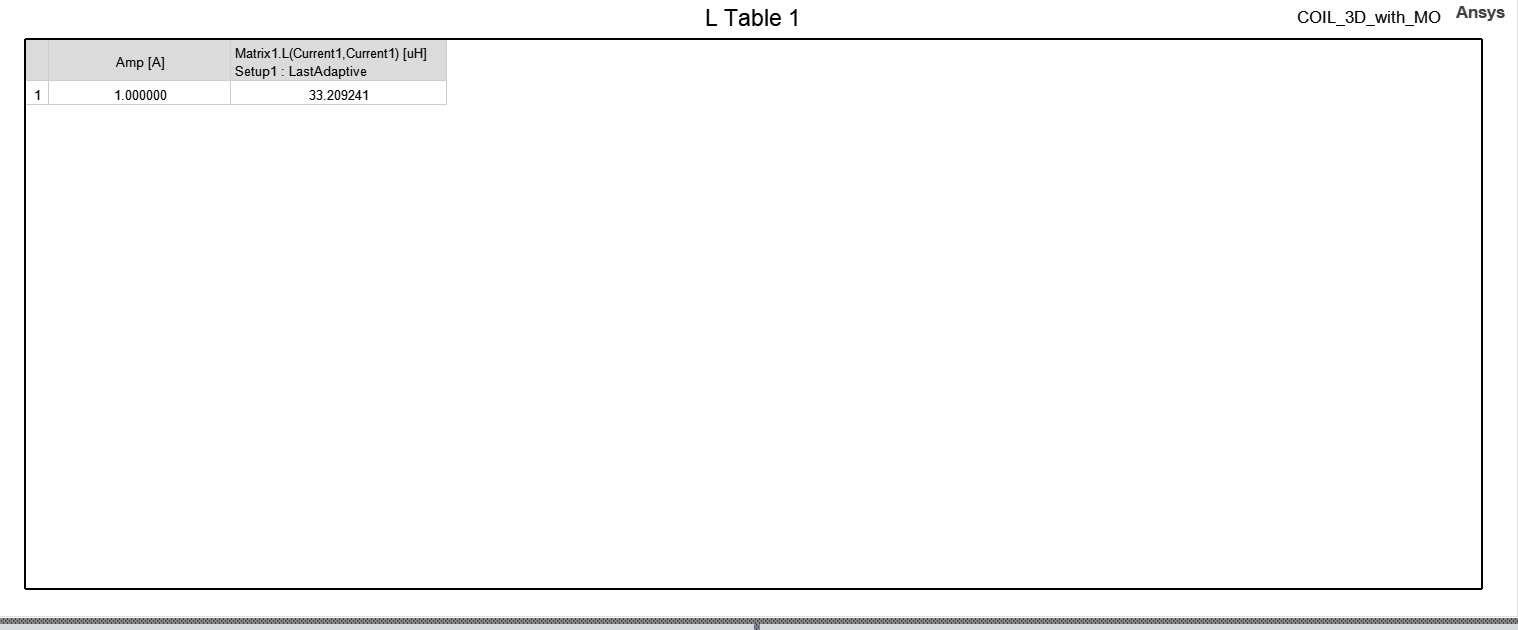
Initially, you said you are simulating only a coil and comparing its inductance with your tested results.
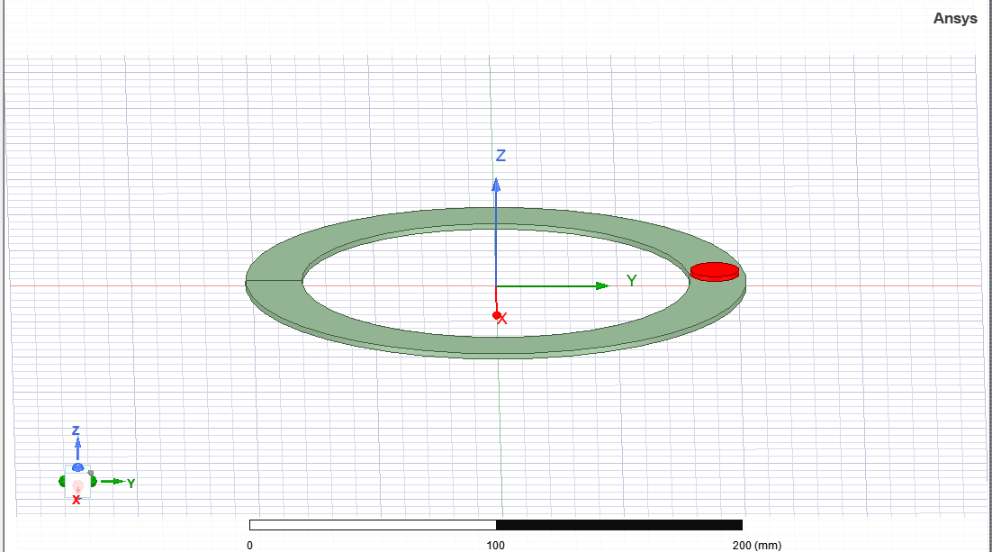
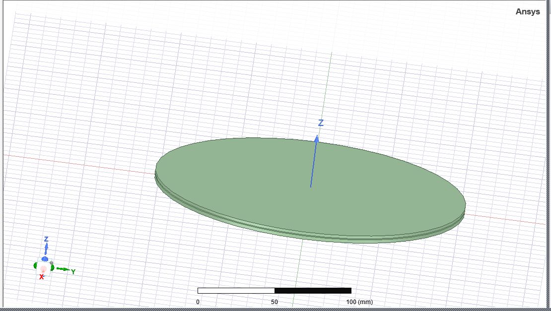
In your previous message, you are saying you are checking the variation in inductance when you bring another metal nearby the coil.Which of the scenarios is correct?Â
If you are talking about the second scenario,
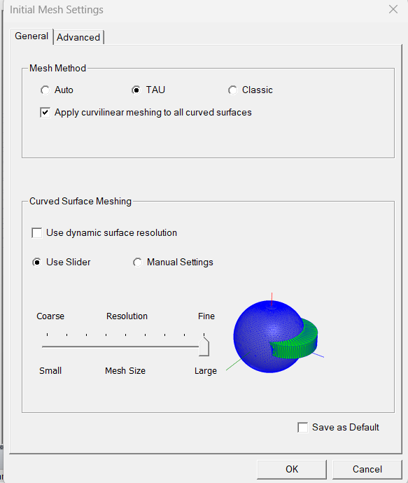
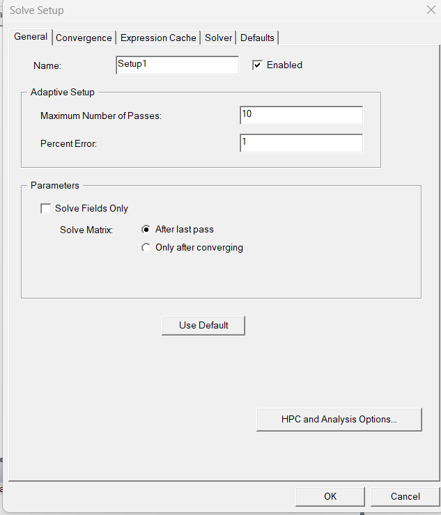
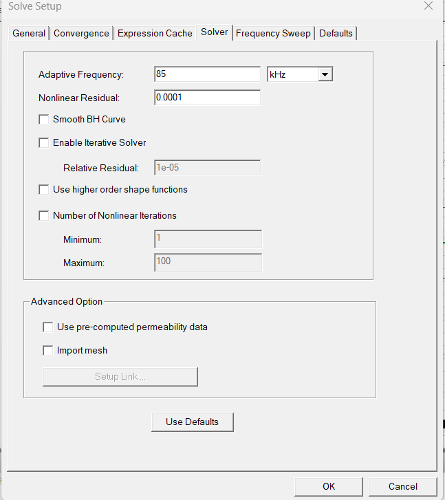
1)Check the eddy current example in Maxwell and make sure you set up everything accordingly.
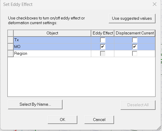
2) Turn on the eddy effect for the necessary parts - Right-click on excitation>set eddy effect
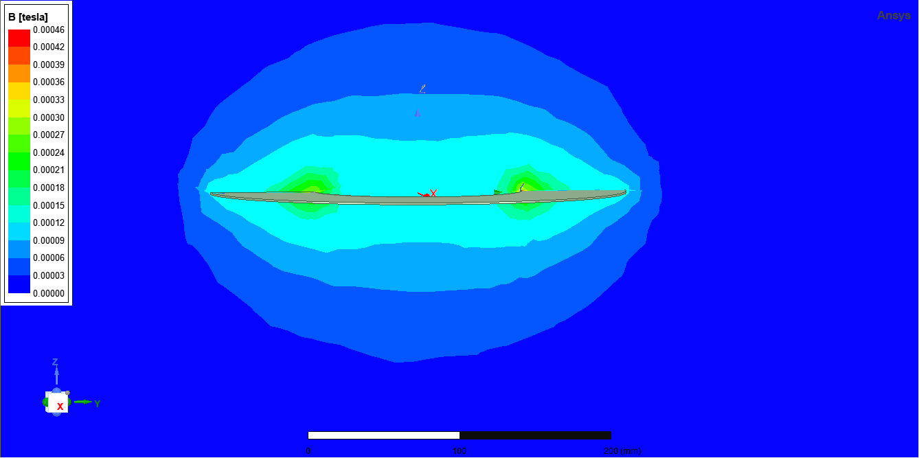
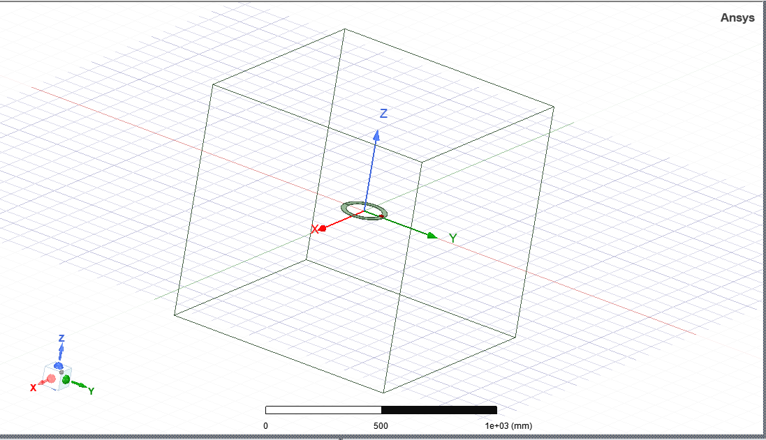
If you are still facing the problem and If you do not share screenshots of your setup including which solution type are you using and the results, how do you expect us to interpret your problem correctly?
How do I know whether you are placing a plate or another coil near the excited coil?Please submit a service request if are subscribed to Ansys customer support.
Â
Regards,
Navya
-
March 16, 2023 at 10:00 am
pradhan.5
SubscriberHi Navya,
Apologies if you are not clear about my problem from the deatails I have provided. The first problem is solved to ceratin extent and I amsatisfied by the obtained results.Â
For the second problem, I have seen the videos that Ansys provides. I have designed the coil in magnetostsic solver first and then copied the model in eddy current solver and added the frequency. My aim is to see how the eddy currents induced in the metal object effects the inductance value of the coil.
The value obtained for inductance in both the cases comes out to be same. I am sharing the images of the model and setting I have used in Magnetostsic slover first. I hope you can be clear about it. MO is metal object and coil in the model, both made from copper
Thanks
Â
Â
Â
Regards
Sushan
-
March 16, 2023 at 10:03 am
-
March 20, 2023 at 12:38 pm
pradhan.5
SubscriberHiÂ
Any updates?
Regards
Sushan
Â
-
March 22, 2023 at 2:44 pm
GLUO
Ansys EmployeeHello Sushan,
Could you try assigning a coil terminal and a winding with explicit turn numbers as the excitation instead of assigning amp*turn current at the terminal?
GLUO
-
March 23, 2023 at 6:06 am
pradhan.5
SubscriberHi GLUO,
I have tried by assigning winding with no. of turns as well but there is no variation in the L value with small metal object as shown in screenshots above. However, when I am using a flat plate covering the entire coil as shown below, there is variation in L value. So, isnt it weird that for a large plate, there is variation in L and not with small coin like object both made of the same material, i.e. copper?
If you want my model, I can share it too.
Regards
SushanÂ
Â
Â
-
March 23, 2023 at 6:34 am
pradhan.5
SubscriberAlso, I found it weird that when I am converting the model with small coin like object to 2D and then analyzing it, there is variation in L value but no variation in the same model in 3D analysis.
So, this has been something I am not really understanding.
Regards
SushanÂ
-
March 24, 2023 at 2:57 pm
GLUO
Ansys EmployeeHello Sushan,
Please submit a service request at ANSYS Customer Portal (Home Page - Ansys Customer Portal). You can share the project file with our dedicated engineers to resolve this issue.
GLUO
-
- The topic ‘Coil design’ is closed to new replies.
- HFSS Incident Plane Wave excitement mode
- How to calculate eddy and hysteresis losses of the core?
- Ansys Maxwell 3D – eddy current
- Simulation of capacitor combining eddy currents with displacement currents
- How to determine initial position in motion setup
- dq graph non-conformity
- Simplorer+Maxwell Cosimulation results and Maxwell results mismatch
- Parametrizing coil “terminals” with coil geometry
- On-chip inductor design
- Maxwell circuit – PWM
-
1602
-
602
-
599
-
591
-
366
© 2025 Copyright ANSYS, Inc. All rights reserved.